| PATENT DRAWINGS |
|
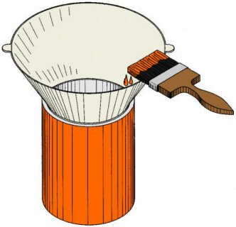
| FIGURE 1 Figure 1 is an illustrative view of the present invention in use. Shown is the present invention installed on a paint can for the purpose of preventing paint from collecting in the paint can rim channel. Additionally the conical shape of the device provides a larger opening for dispensing the paint from the paint can as well as pouring the paint back into the paint can as from a roller tray.
|
|
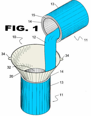
| FIGURE 2 Figure 2 is an illustrative view of the present invention in use. Shown is the installed device being used in a typical paint application process. Normally, when applying paint by brush, the tendency is to extract excess paint by wiping the brush on the paint can interior rim. This often causes an undesireable accumulation in the paint can rim channel, interfering with the hermetic seal of the paint can, rendering long term storage useless. The conical shaped device of the present invention seals the paint lid-closing channel while providing an edge and interior work surface.
|
|
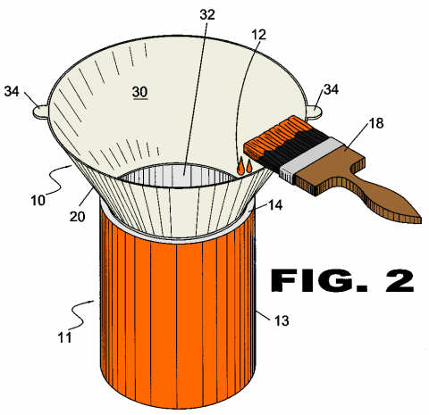
| FIGURE 3 Figure 3 is a perspective view of the present invention. The present invention has two lifting tabs aligned with the uppermost horizontal surface positioned roughly 180 degrees apart. These serve to facilitate positioning of the device atop a paint can and also to allow convenient removal without having to come in contact with the surfaces that may contain wet paint.
|
|
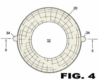
| FIGURE 4 Figure 4 is a top view of the present invention. The lower base of the device contains an aperture allowing for passage of paint into and out of the paint can. It is conveniently sized to overlap the paint can rim channel structure so as to further prevent possibility of contamination.
|
|
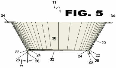
| FIGURE 5 Figure 5 is a cross sectional view of the conical device of the present invention. Shown is the exterior side of the paint can closure channel engaging member having a slope whereby the engaging member has a tapered side so that the engaging member will seat within the channel even though the channel may differ in distance across the rim of the channel.
|
|
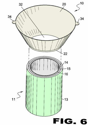
| FIGURE 6 Figure 6 is a perspective view of the present invention with a paint can positioned immediately beneath. The present invention has a flange portion conforming substantially to the paint can rim channel thereby forming a seal with the can.
|
|
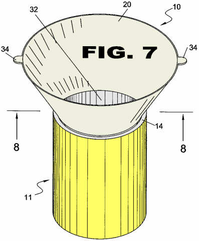
| FIGURE 7 Figure 7 is a perspective view of the present invention in operating position atop a paint can. Shown is the conical device having oppositely opposed tabs located on the upper periphery acting as handles for attaching and removing the device from a paint can.
|
|
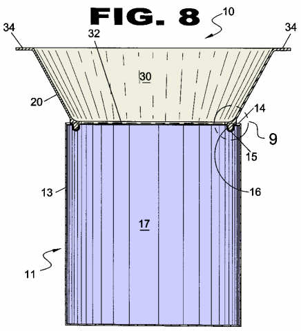
| FIGURE 8 Figure 8 is a cross sectional view of the present invention in use. Shown is a cross sectional view of the present invention mounted on a typical paint can, whereupon the conical shape of the invention increases the effective opening of the paint can. In addition, the engaging member of the invention is seated in the rim channel preventing paint from accumulating in the rim channel.
|
|
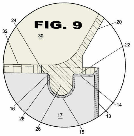
| FIGURE 9 Figure 9 is an enlarged view of the conical device flange portion shown in mating position with the paint can rim channel. The engaging member and shoulders of the flange portion form a mating seal with the paint can rim channel thereby no paint can enter said channel. The flange at the base of the device is sized to extend beyond the innermost lip of the paint can rim channel whereby any paint on the walls will drip into the interior of the can instead of running down the sides.
|