 |
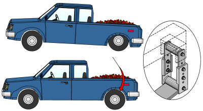
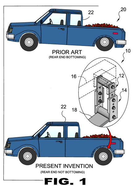
| FIGURE 1 FIGURE 1 is an illustrative view of prior art 20 and of the present invention 10. The present invention is a lift support system for light trucks 10, which is adjustable to elevate the rear of a light truck 22 or other such vehicle to a needed height depending on the demand of the user. The system comprises an upper chassis attachment assembly 12 that fastens to the chassis 16 and a lower leaf spring attachment assembly 14 that is secured to the leaf spring 18 of the suspension system to lift the bed of the vehicle.
|
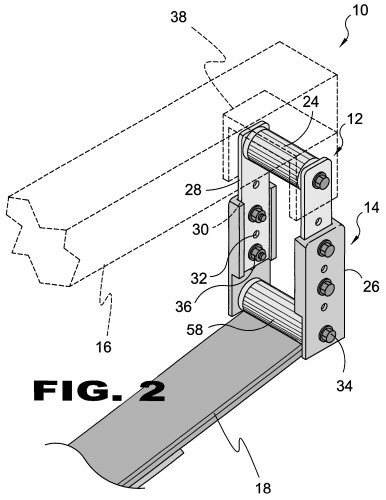 |
| FIGURE 2 FIGURE 2 is a perspective detail view of the lift support system 10 for light trucks, which is adjustable to elevate the rear of a light truck to a needed height depending on the demand of the user. The present invention 10 provides a leaf spring attachment assembly 14 that is selectively attachable to a mating chassis attachment assembly 12. The leaf spring attachment assembly 14 comprises a pair of substantially U-shaped receiving bars 26. The chassis attachment assembly 12 comprises a bushing 24 with a pair of substantially flat, elongate extension bars 28 extending perpendicularly downward from the ends of their respective bushing 24. The extension bars 28 are positioned and dimensioned to reside within the channels 30 defined by the U-shaped configuration of the receiving bars 26. A plurality of coaligned fastening apertures 32 linearly disposed along the lengths of the receiving bars 26 and the extension bars 28 for receiving bolt 34 and nut 36 fasteners to adjoin the two assemblies together. The bushing 24 of the chassis attachment assembly 12 is bolted to the leaf spring bracket 38 integral with the chassis 16 and the receiving bars 26 of the leaf spring attachment assembly 18 are bolted to the eyelet of the leaf spring 38.
|
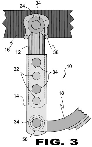 |
| FIGURE 3 FIGURE 3 is an orthographic view of the present invention 10. Shown is the lift support system for light trucks 10 which is adjustable to elevate the rear of a light truck to a needed height depending on the demand of the user. The bushing 24 of the chassis attachment assembly 12 is retained within the leaf spring bracket 38 of the chassis 16 and the leaf spring attachment assembly 14 is fastened to the eyelet 58 of the leaf spring 18 with a bolt 34 placed through the selected fastener apertures 32.
|
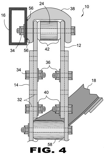 |
| FIGURE 4 FIGURE 4 is a rear view of the present invention10. Shown is the lift support system for light trucks 10 which is adjustable to elevate the rear of a light truck to a needed height depending on the demand of the user. The bushing 24 of the chassis attachment assembly 12 is retained within the leaf spring bracket 38 riveted 56 to the chassis 16 and the receiving bars 26 of the leaf spring attachment assembly 14 is fastened to the eyelet 58 of the leaf spring 18 with a bolt 34 placed through the selected fastener apertures 32 and secured thereto with a nut 36 and washer 40. A plurality of spacers 42 of varying thicknesses are provided to adapt the length of the bushing 24 accordingly to the vehicle.
|
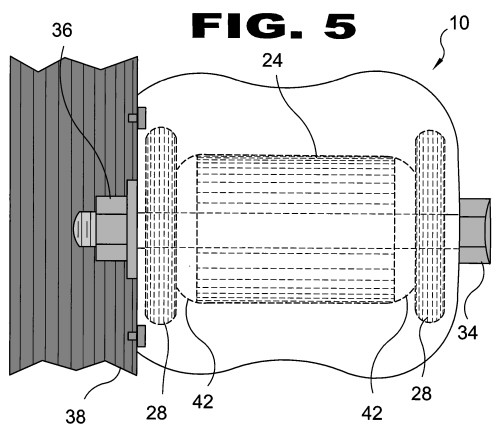 |
| FIGURE 5 FIGURE 5 is a top view of the present invention 10 showing the bushing 24 of the chassis attachment assembly 12 fastened to the leaf spring bracket 38 of the chassis with a bolt 34, nut 36 and washer 40 assembly. The extension bars 28 are bolted on the side of the spacers 42 opposing the bushing 28.
|
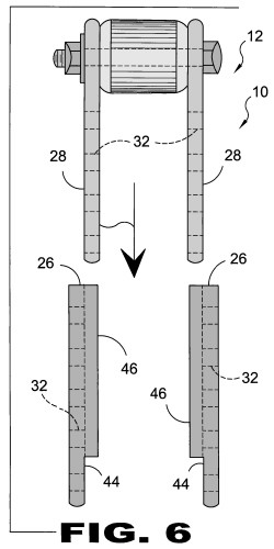 |
| FIGURE 6 FIGURE 6 is a view of the lift support system of the present invention 10. Shown is a fully assembled chassis attachment assembly 12 and the receiving bars 26 of the mating leaf spring attachment assembly. The receiving bars 26 comprise a main plate 44 with sidewalls 46 depending from opposing edges thereof that form the channel to receive the extension bars 28 of the chassis attachment assembly 12. Also shown are the fastener apertures 32 disposed in the main plate 44 of the receiving bar 26 and in the extension bar 28. The alignment of the apertures 32 of the associated bars determine the length of the lift support 10 once bolted together.
|
 |
| FIGURE 7 FIGURE 7 is a view of the present invention 10 demonstrating the relationship between the inner side 48 of the receiving bar 26 and the extension bar 28. The sidewalls 46 depending from the main plate 44 define the channel 30 that receives the extension bar 28 therein and the overall length thereof is determined by the alignment of the fastener apertures 32.
|
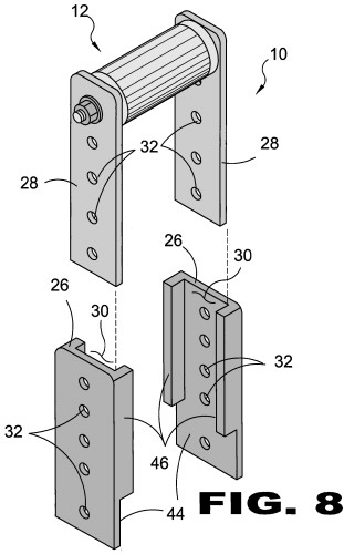 |
| FIGURE 8 FIGURE 8 is a perspective view of the present invention 10. Shown is a fully assembled chassis attachment assembly 12 and the receiving bars 26 of the mating leaf spring attachment assembly. The receiving bars 26 comprise a main plate 44 with sidewalls 46 depending from opposing edges thereof that form the channel 30 to receive the extension bars 28 of the chassis attachment assembly 12. Also shown are the fastener apertures 32 disposed in the main plate 44 of the receiving bar 26 and in the extension bar 28.
|
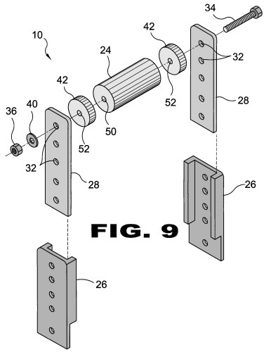 |
| FIGURE 9 FIGURE 9 is an exploded view of the chassis attachment assembly 12 and the mating receiving bars 26. The bushing 24 is united by a bolt 34 passing through the top fastener aperture 32 of the extension bars 28 and the central spacer throughbore 52 in the spacers 42 and the central bushing throughbore 50.
|
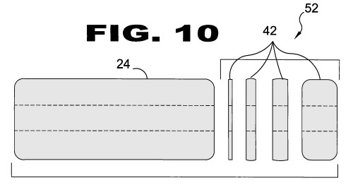 |
| FIGURE 10 FIGURE 10 is an orthographic view of the cylinder kit 54 of the present invention. Shown are the bushing 24 and spacers 42 of different sizes used to adapt the cylinder kit 54 to a light truck's leaf spring.
|