 |
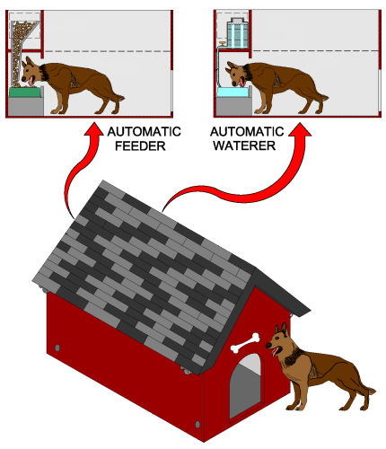
| FIGURE 1 Figure 1 is an illustrative view of the present invention in use. The present invention is a pet shelter with automatic feeding and watering stations 10 that are preferably 10 inches from the floor and 12 inches deep with a roof 14 hingedly attached to the main housing 12 and secured in a closed position on one side of the housing by latches 16. When said latches 16 are disconnected, the roof 14 can be swung open for easy access to the interior. Within the back interior wall 18 of the pet shelter are two side by side compartments. One side provides an automatic food dispense r 20 that fills as the pet eats and the other side has an automatic water dispenser 22. Both compartments are accessed through an opening on the water compartment side. The water dispenser 22 has tubing 24 with an on/off valve 26 that runs from the water storage reservoir 28 down into the water dish 30. The valve 26 is shut off when the water dish 30 is refilled. The remaining portion of the interior structure is housing for the pet 32. A plurality of apertures 34 are disposed around the base of the housing 12 for receiving anchors to secure the shelter to the ground.
|
 |
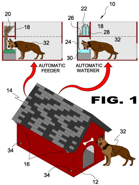
| FIGURE 2 Figure 2 is a perspective view of the present invention. Shown is the exterior of the pet shelter with automatic feeding and watering stations 10 with a roof 14 attached to the main housing 12 by hinges 36 and secured in a closed position on the other side of the housing 12 by latches 16. When said latches 16 are disconnected, the roof 14 can be swung open for easy access to the interior. Also shown are base approximate apertures 34 for inserting anchors to prevent displacement of the pet shelter by the pet or weather conditions.
|
 |
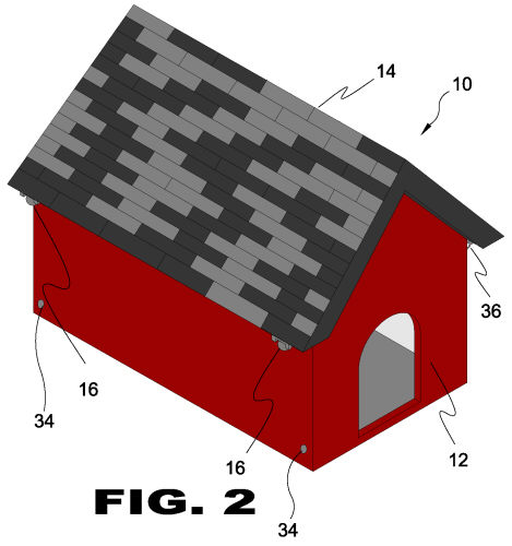
| FIGURE 3 Figure 3 is a perspective view of the present invention. Shown is the pet shelter with automatic feeding and watering stations 10 with the roof 14 in an open position being attached to the main housing 12 with hinges 36 and secured in a closed position on one side of the housing by mating latch members 16. When said latches 16 are disconnected, the roof can be swung open for easy access to the interior. The housing 12 includes an entrance 38 and an interior back wall 18 with an interior water compartment access recess 40 leading to the water supply compartment 44 and an interior feeding access recess 42 leading into the food supply compartment 46.
|
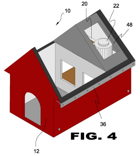 |
| FIGURE 4 Figure 4 is a perspective view of the present invention. Shown is the pet shelter with automatic feeding and watering stations 10 with roof removed from the hinge 36 for clarity from the main housing 12. There is an upper access opening 48 to provide access to fill the food dispenser 20 and the water dispenser 22.
|
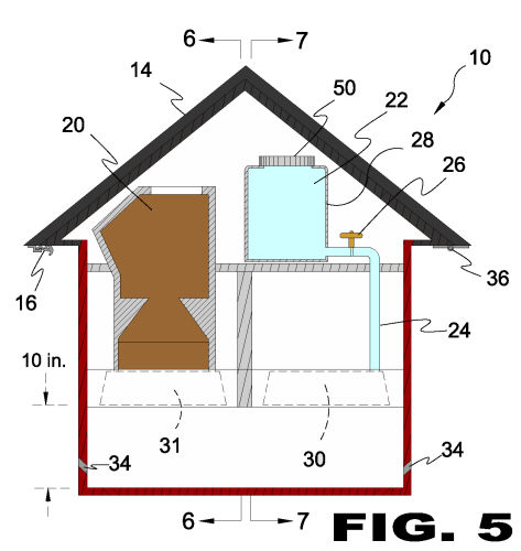 |
| FIGURE 5 Figure 5 is a sectional view of the present invention. Shown is the pet shelter with automatic feeding and watering stations 10 that are preferably 10 inches from the floor and 12 inches wide having a roof 14 hingedly 36 attached to the main housing 12 and secured in a closed position on one side of the housing by latches 16. Provided is an automatic food dispenser 20 that fills a food dish 31 through a hopper as the pet eats. An automatic water dispenser 22 comprising a water storage reservoir 28 and threaded cap 50 with water flow tubing 24 leading to the water dish 30. The tubing 24 has an automatic on/off valve 26 that regulates gravity feeding of water from the reservoir 28 to the water dish 30. Anchor apertures 34 enable the user to anchor the shelter to the ground.
|
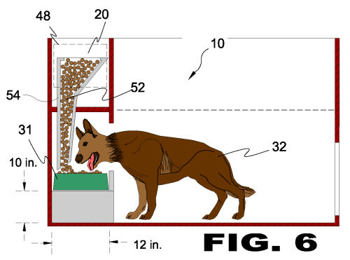 |
| FIGURE 6 Figure 6 is a side sectional view of the present invention. Shown is the pet shelter with automatic feeding and watering stations 10 illustrating the food dispenser 20 wherein pet food 52 is introduced through the upper access opening 48 into the hopper 54 and delivered to the food dish 31 for the pet 32 to eat.
|
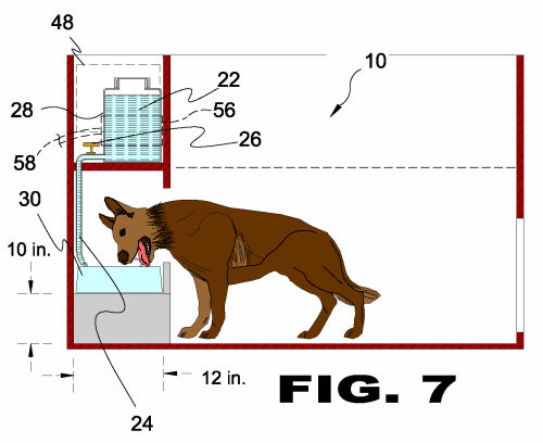 |
| FIGURE 7 Figure 7 is a side sectional view of the present invention. Shown is the pet shelter with automatic feeding and watering stations 10 that are preferably 10 inches from the floor and 12 inches deep with the water station having an automatic water dispenser 22 accessed through an upper access opening 48. The water dispenser 22 has tubing 24 with an on/off valve 26. The tubing 24 runs from the water storage reservoir 28, down into the water dish 30. The valve 26 is shut off when the water dish 30 is refilled. An optional heating element 56 and power cord 58 may be employed to prevent the water from freezing during cold weather.
|
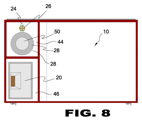 |
| FIGURE 8 Figure 8 is a top sectional view of the present invention. Shown is a top view, looking into the pet shelter with automatic feeding and watering stations 10. On the back interior wall of the pet shelter are two compartments, side by side. Depicted are the food supply compartment 46 with automatic food dispenser 20 and the water supply compartment 44 with automatic water dispenser 22 comprising a reservoir 28 with a threaded cap 50, water flow tubing 24 and an on/off water valve 26.
|