Shoe Storage Device

*****New Patent For Sale, Licensing, Manufacturing, and/or Investors*****

U.S. Patent : # 6,598,948 click here for full text patent document

Inventor : Jonathan L. Harmon

invention uses
prototype pics
patent drawings
contact info
invention.net

new invention

As attorney for the inventor of the innovative Shoe Storage Device we are currently seeking manufacturing companies to license, purchase patent rights or enter into a royalty agreement for this timely invention.

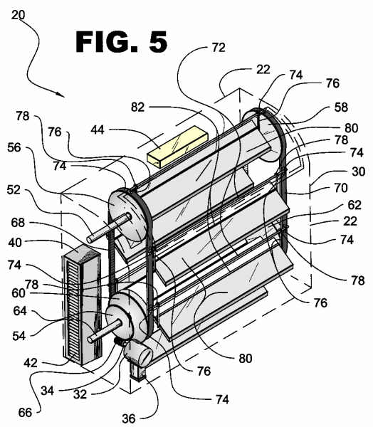
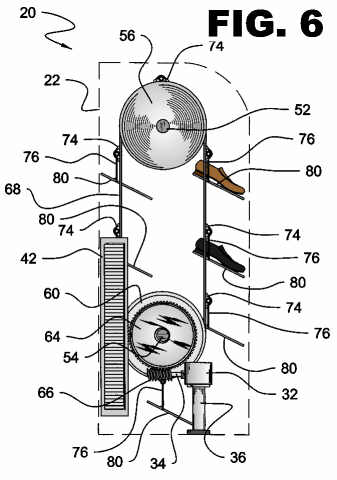
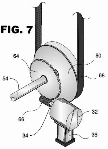
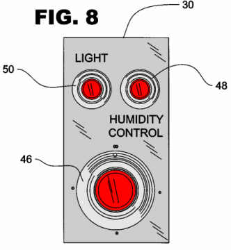
Objects of the present invention:

The following pictures are meant to display possible physical characteristics of the present invention and are not to be taken in a limiting sense. It is understood that other embodiments may be utilized and that structural changes may be made without departing from the scope of the invention.
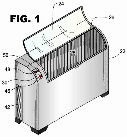
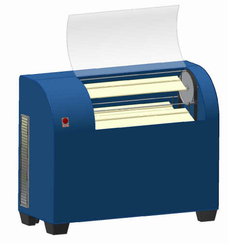
Prototype Pictures


new invention
Figure A - Front Angled View


new invention
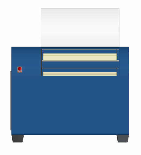
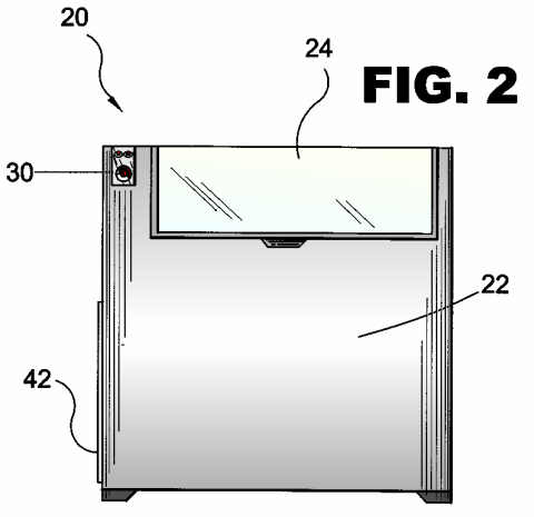
Figure B - Front View


new invention
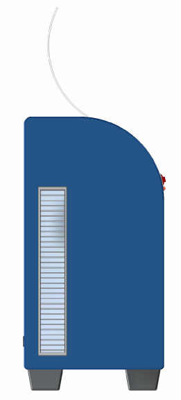
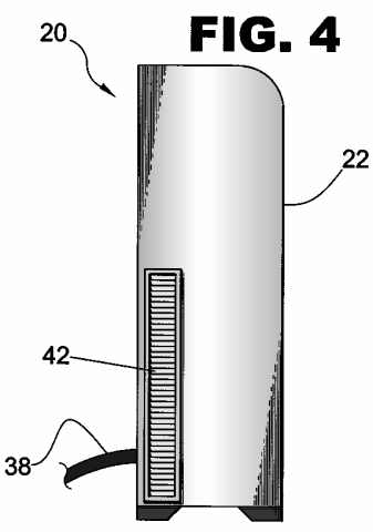
Figure C - Side View
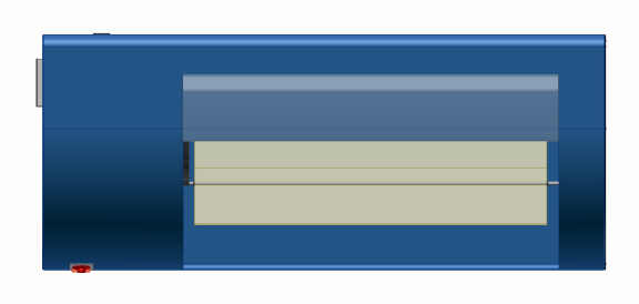
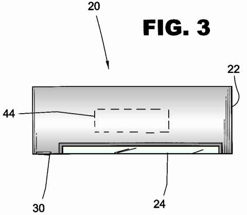

new invention
Figure D - Top View


new invention
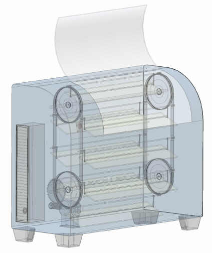
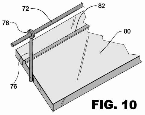
Figure E - Angled Mechanical View


new invention
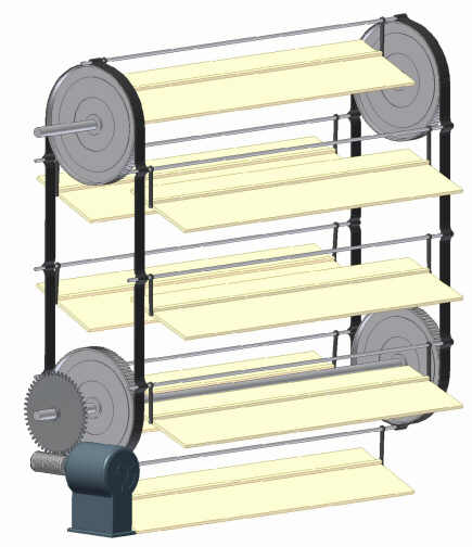
Figure F - Angled Shelf View


new invention
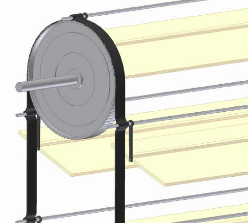
Figure G - Pulley Detailed View


new invention
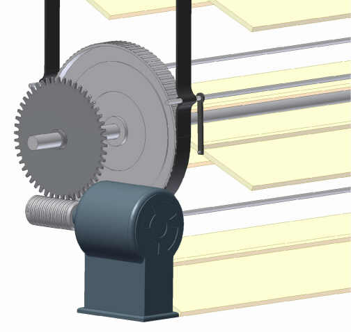
Figure H - Motor Detailed View

LIST OF REFERENCE NUMERALS
20 present invention 54 second shaft
22 housing56 first shaft first pulley
24 transparent housing door 58 first shaft second pulley
26 housing door hinge60 second shaft first pulley
28 housing interior 62 second shaft second pulley
30 control panel64 sprocket gear
32 motor 66 worm gear
34 motor shaft68 first belt
36 motor vibration damper 70 second belt
38 power cord72 dispaly assembly rod
40 humidifier 74 rod connectors
42 humidifier ventilation grill76 rod suspension member
44 light assembly 78 suspension member bearing
46 motor control knob80 display assembly platform
48 humidifier control knob 82 platform elevation
50 light assembly control knob100 shoes
52 first shaft

PATENT DRAWINGS
patent drawing
FIGURE 1

Figure 1 is a perspective view of the present invention. Shown is an exterior view having a humidity-controlled enclosure used to preserve shoes.

patent drawing
FIGURE 2

Figure 2 is a front view of the present invention. The shoe preserver has a housing with a transparent hinged access panel for inserting and removing shoes therefrom. An exterior control panel provides for controlling the rotating shelves and the humidifier.

patent drawing
FIGURE 3

Figure 3 is a top view of the present invention. This drawing depicts the location of the lighting unit shown in outline. When the access door is opened the light will illuminate.

patent drawing
FIGURE 4

Figure 4 is a left exterior view of the present invention. This view shows the location of the louvered vents for the humidifier and an electrical connection for power.

patent drawing
FIGURE 5

Figure 5 is a perspective view of the interior mechanism of the present invention. Shown is a plurality of display platforms connected to spaced away belts having rotative elements connected by gears to a motor whereby the display platforms can be selectively positioned adjacent a hingedly connected transparent access hatch.

patent drawing
FIGURE 6

Figure 6 is a side view of the present invention. Shown is a motor having a worm gear engaging a sprocket gear that turns a first shaft, which then turns a pair of pulleys with transmission belts extending to another pair of pulleys. The belts have a plurality of shelves attached thereto whereby one or more pairs of shoes can be selectively positioned thereon. Also shown is the humidifier used to control humidity within the apparatus.

patent drawing
FIGURE 7

Figure 7 is an enlarged view of the gear assembly of the present invention.

patent drawing
FIGURE 8

Figure 8 is an enlarged view of the control panel having controls for the motor, light assembly and humidifier.

patent drawing
FIGURE 9

Figure 9 is an enlarged drawing of a shoe display platform of the present invention. The elevated heel stop and the suspension members are permanently affixed to the platform and are supported by a rod that is freely rotatable by use of bearings.

patent drawing
FIGURE 10

Figure 10 is a partial view of the shoe display platform with an enlarged view of the suspension member bearings. The bearings allow free rotation of the suspension members and allows the shelf to keep an approximately forty-five degree angle while rotating.

top

If you are interested in licensing, purchasing the rights to the above invention or entering into a royalty agreement please contact the office of Michael I. Kroll as follows:

Michael I. Kroll
80 Skyline Drive, Suite 304
Plainview, New York 11803
Tel. #: 800-367-7774
Tel. #: 516-367-7777
Fax #: 800-367-7999
Fax #: 516-802-0510
E-Mail patent@invention.net

patent attorney home page