The following patent is currently for sale or license by the inventor. If you are interested in making an offer or would like more information please contact the attorney at the numbers listed on the bottom of this page.
The present invention relates generally to jumping toys and, more specifically, to a bug-like flipping toy having four resilient leg members extending from a substantially horizontal body member with a depression member in the form of an extended posterior position that, when an external force is applied thereupon, will deform the leg members and create reciprocal tension between the surface that the toy is on and the body member until the external force is removed allowing the front legs to recoil and propel the anterior body portion upward as the two posterior legs rebound to their original position thereby launching the present invention tumbling into a horizontal and vertical trajectory.
As attorney for the inventor of the innovative Bug-like Flipping Toy we are currently seeking manufacturing companies to license, purchase patent rights or enter into a royalty agreement for this timely invention.
Click on the picture to the left to view a short video presentation of the Bug-like Flipping Toy in action. (windows media required)
to provide a flipping bug-like toy having anterior legs with a generally horizontal width that extend acurately forward and downward from the body member so the legs will flatten and extend when compressed
to provide a a flipping bug-like toy having a body with a depression member for the user to exert pressure upon, thereby deforming the legs and creating the potential power for the projection that will occur once the external pressure is removed
to provide a toy that is fun and easy to use and economical in cost to manufacture
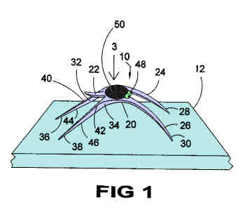
Figure 1 is a perspective view of the present invention on a flat surface ready for use.
FIGURE 2
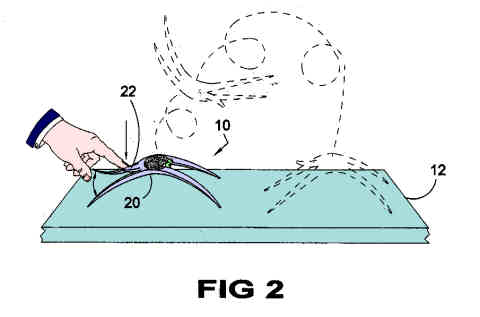
Figure 2 is a perspective view of the present invention in use. Shown is an external force being applied to the depression member causing the posterior leg members to sepatate to create the potential energy for propulsion.
FIGURE 3
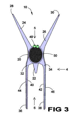
Figure 3 is a top view of the present invention.
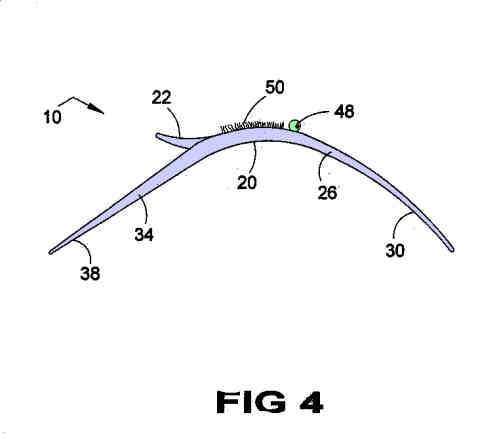
FIGURE 4
Figure 4 is a side view of the present invention taken from Figure 3 as indicated.
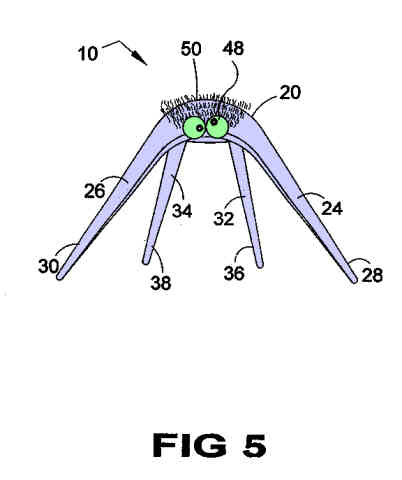
FIGURE 5
Figure 5 is a front view of the present invention taken from Figure 3 as indicated.
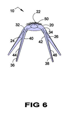
FIGURE 6
Figure 6 is a rear view of the present invention taken from Figure 3 as indicated.