| LIST OF REFERENCE NUMERALS |
| 10 Present Invention |
32 Wiring |
| 12 Light Bulb |
34 Connector |
| 14 Light Globe |
36 Drip Barrier Contour |
| 16 Light Shield |
38 Sidewall |
| 18 Photo Sensor |
40 Soil Level
|
| 20 Socket |
42 Splash Guard |
| 22 Base |
44 Control Mechanism |
| 24 Plant |
46 Reflective Material |
| 26 Plant Container |
48 Bottom |
| 28 Transformer |
50 Lens |
| 30 Support |
52 Plug |
|
| PATENT DRAWINGS |
 |
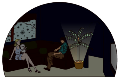
| FIGURE 1 Figure 1, is an illustrative view of the present invention 10 in use. The present invention 10 is a plant and room illumination apparatus comprising a plurality of illuminable fixtures where each fixture includes an anchor 30, a socket 20, a base 22, a light bulb 12 or other illumination source, a light globe 14, and a light shield 16. The light globe 14 provides protection to the light bulb 12 or to the illumination source. The light globe 14 is preferably made of a durable plastic material that is capable of with standing the heat generated by the light bulb 12 or illumination source yet allowing the light from the source to pass there through. The plastic may be transparent (i.e. clear or without color), the plastic may be translucent, or the plastic may be colored or tinted to give off colored light. It is envisioned that the colored or tinted light globes 14 would be translucent to allow the light from the bulb 14 or source to pass there through. The light globes 14 may employ any color, which may be desired by the user. The light globes 14 may be all of the same color or be different colors depending on the desires of the user. A strand of lights may employ light globes 14 with a plurality of colors or a single color. It is envisioned that the light globes 14 may be easily changed or replaced by the user depending on their needs. The light globe 14 protects the light bulb 12 from contact with water, debris, and from contact with a user. The present invention 10 incorporates a photo sensor 18 that detects the amount of ambient light available and turns on the lights when the ambient light drops is at or below a set level and turns off the lights when the ambient light is above a set level. The photo sensor 18 is essentially a switch controlled by an ambient light sensor. The photo sensor 18 continually detects the amount of ambient light available and turns on the lights when the amount of ambient light drops to or below an established level or threshold. The anchor 30 is designed to support its attached fixture in an upright position when the support is placed or inserted into the soil in the plant container. The support 30 may be in the form of a stake that is stuck or inserted into the soil in the container. The anchor 30 may also be a threaded anchor that may be screwed into the soil to provide a more positive means for anchoring the each fixture.
|
 |
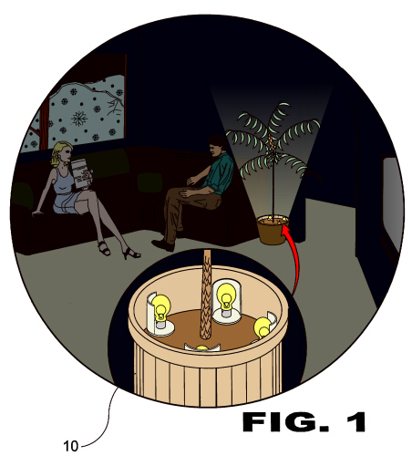
| FIGURE 2 Figure 2, is an illustrative view of the present invention 10 in use. Shown is one embodiment of the present invention 10, a plant and room illumination apparatus comprising a plurality of illuminable fixtures connected by electrical wiring 32. A strand or string of lights includes a plurality of illuminable fixtures secured together by appropriate wiring 32 or a suitable power cord. It is envisioned that the fixtures may be permanently secured to the wiring 32 or cord in such a manner that they are not removable from the wiring 32 or cord or they may be made so that they can be quickly and easily attached and removed from the wiring 32 or the cord. It is envisioned that the apparatus employ a transformer 28 and the light bulbs 12 are powered by low voltage to reduce the potential injury to a user. Low voltage is well known in the electrical arts. It is also envisioned that the apparatus may employ a control mechanism 44 which is capable of turning on and off the lights in sequence or other manners to include but not limited to flashing or flickering. Each light shield 16 aids in directing the light away from its respective light bulb 12 or illumination source. The light shields 16 may be opaque and will block light from passing there through. In addition the light shields 16 may be provided with a reflective material 46 to aid in directing light away from the shields 16. The light shields 16 seen in Fig. 2 have a curved or arcuate light-directing surface. This surface focuses and directs light away from the shield. The light-directing surface is the surface that faces the light bulb 12 and light globe 14. It is also envisioned that the base 22 may employ a reflective coating in its upper surface. This will aid the base 22 is directing and focusing light upwards and away from the upper surface of the base 22. The bases 22 are shown as being substantially planar surfaces but may employ a curved or parabolic surface for directing or focusing the light from the illumination sources. It is also envisioned that the reflective surface of the bases 22 and the shields 16 may be smooth or in the alternative may employ a rough or irregular surface. The rough or irregular surface will tend to diffuse any light reflected there from. The reflective surfaces of the shields 16 and the bases 22 send light upward and outward away from the light bulbs 12. It is envisioned that the shields 16, the bases 22, and the supports 30 be made from a durable plastic material and may be molded together in one piece or they may be formed of individual pieces joined or secured together. In the alternative the light fixtures (shield, base and supports) may be made of a metal or any other suitable material.
|
 |
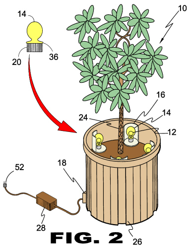
| FIGURE 3 Figure 3, is a perspective view of the present invention 10. Shown is a string or stand of lights of the present invention 10. The strand of lights includes a plurality of illuminable fixtures, a power cord or wiring 32 interconnecting the fixtures, a photo sensor 18, and a transformer 28. The strand of lights is for use with an existing plant container 26 or may be formed as part of a plant container 26 (see Figures 8 and 9). Either embodiment employs a plurality of illuminable fixtures each fixture having a support 30 secured thereon or formed therein. In the first embodiment the supports 30 are separate from the plant container 26 and are capable of holding the fixture upright when the support 30 is inserted into the soil in the plant container 26. In the second embodiment the supports 30 are formed as part of the plant container 26. The supports 30 secure the light sockets 20 to the plant container 26. Either embodiment may employ a photo sensor 18, a transformer 28, and a control mechanism 44. The control mechanism 44 is capable of performing a variety of special effects such as but not limited to varying the intensity of each light bulb 12 (i.e. dimming), causing the light bulbs 12 to flicker or flash, causing the light bulbs 12 to light in a particular sequence, or any combination thereof. It is envisioned that the control mechanism 44 employ a microprocessor that is user programmable to allow the user to control the lights as desired. The support 30 or anchor in the first embodiment may simply be a stake that is inserted into the soil (commonly referred to as potting soil) that is disposed in plant container 26. It is also envisioned that the support 30 may be a screw support or anchor that has a threaded portion that is screwed into the soil in the plant container 26. Each support 30 is capable of supporting its respective fixture in an upright position when the support 30 is inserted or placed into the soil in the plant container 26.
|
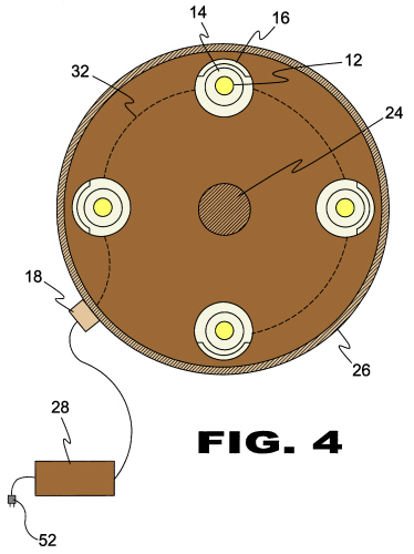 |
| FIGURE 4 Figure 4, is a top view of the present invention 10. Shown is a strand of lights that is separate from the plant container 26. The strand are typically employed with or retrofitted into an existing plant container 26. The transformer 28 and the photo sensor 18 are shown on the exterior of the container 26 but may be located inside the container 26. The transformer 28, the photo sensor 18, and wiring 32 will be fully waterproof when they are intended to be placed inside the container 26 to prevent the possibility of damage when the plant 24 is watered. It is envisioned that the device may also include a Ground Fault Interrupt (GFI) to prevent the possibility of electrical short circuit in the wet environment. The GFI may be incorporated into the plug portion of the electrical cord. It is known to provide a GFI in the portion of the cord that plugs into the outlet. The GFI may be positioned between the outlet and the transformer. The photo sensor 18 is shown as being positioned on the exterior surface of the container sidewall 38 and is attached to the wiring 32 or cord between the transformer 28 and the light fixtures. It is envisioned that the photo sensor 18 may be positioned in other locations as desired by the user. It is also envisioned that the photo sensor 18 may be intergraded into or made part of the transformer 28. It is preferable that the photo sensor 18 will be positioned in an exposed surface of the transformer 28 to ensure that it will be exposed to the ambient light of the room in which it is located. It is also envisioned that the photo sensor 18 may be positioned in the wiring 32 or cord between the transformer 28 and the plug 52. The plug 52 is the part of the cord that plugs into the household outlet. The photo sensor 18 is preferably located so that it is not affected by the light from the light bulbs 12. It is desirable to place the sensor 18 such that when the lights bulbs 12 are illuminated they do not cause the photo sensor 18 to turn them off.
|
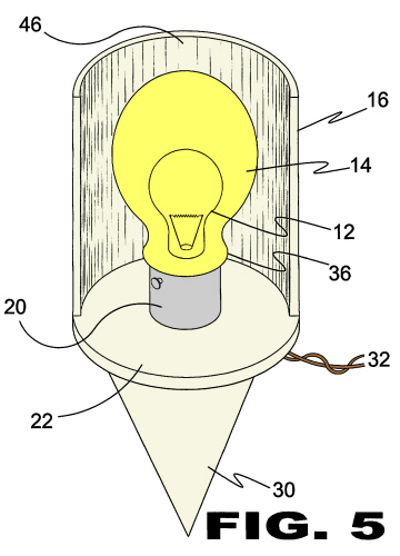 |
| FIGURE 5 Figures 5 and 6 are perspective front and side views (respectively) of a single light fixture of the present invention 10. The single light fixture is one of a plurality of fixtures on a strand or string of lights. The strand or string of light fixtures is for use with or may be retrofitted into an existing plant container 26. It is envisioned that the user will be required to make a hole in the sidewall 38 of the container 26 to allow the cord or wiring to pass there through. It is not necessary to have the cord pass through the container 26 but may be desirable since it will hide the wiring 32 or cord. It is envisioned that the user employ a gasket or caulk to seal the hole made in the container 26. It is envisioned that the cord or wiring 32 may be provided with a connector 34 (see Fig. 3) that is waterproof to allow the user to separate the cord or wiring 32 into two pieces. Thus making it easier to pass the wiring 32 through the hole or opening in the container 26. The connector 34 will be readily separable to allow the user to pass one part of the connector 34 through the hole or opening and then connect it to the other part of the connector 34 secured to or formed in the other part of the cord or wiring 32. Thus the user only has to make a hole large enough to allow the connector 34 to pass there through. The user will then seal the opening in the container 26 to prevent water from leaking there through when the plant 24 is watered. The container 26 will typically be modified when empty. Once the caulk or other sealant has dried the user can place a plant and its associated potting soil in the container 26 and distribute the light fixtures about the container 26 as desired.
|
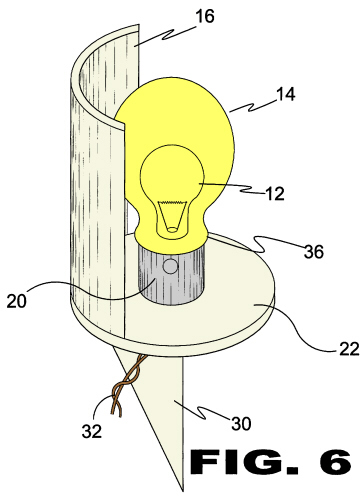 |
| FIGURE 6 Figures 5 and 6 are perspective front and side views (respectively) of a single light fixture of the present invention 10. The single light fixture is one of a plurality of fixtures on a strand or string of lights. The strand or string of light fixtures is for use with or may be retrofitted into an existing plant container 26. It is envisioned that the user will be required to make a hole in the sidewall 38 of the container 26 to allow the cord or wiring to pass there through. It is not necessary to have the cord pass through the container 26 but may be desirable since it will hide the wiring 32 or cord. It is envisioned that the user employ a gasket or caulk to seal the hole made in the container 26. It is envisioned that the cord or wiring 32 may be provided with a connector 34 (see Fig. 3) that is waterproof to allow the user to separate the cord or wiring 32 into two pieces. Thus making it easier to pass the wiring 32 through the hole or opening in the container 26. The connector 34 will be readily separable to allow the user to pass one part of the connector 34 through the hole or opening and then connect it to the other part of the connector 34 secured to or formed in the other part of the cord or wiring 32. Thus the user only has to make a hole large enough to allow the connector 34 to pass there through. The user will then seal the opening in the container 26 to prevent water from leaking there through when the plant 24 is watered. The container 26 will typically be modified when empty. Once the caulk or other sealant has dried the user can place a plant and its associated potting soil in the container 26 and distribute the light fixtures about the container 26 as desired.
|
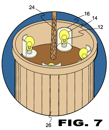 |
| FIGURE 7 Figure 7, is a detailed view of the present invention 10 showing how the fixtures are positioned within an existing plant container 26. The fixtures are preferably positioned so that the light shields 16 are spaced from the sidewall 38 of the container 26. This prevents or ensures that that the light shields 16 are not in contact with the sidewall 38 of the container 26. The plant container 26 plastic may not be heat resistant and may be melted by the heat generated by the light bulbs 12. It is envisioned that the bulbs 12 may be incandescent, florescent, light emitting diodes (LEDs), or any other suitable type of bulb 12. It is also envisioned that the present invention 10 may employ a string or strand of interconnected light sources that are protected by a sealed plastic tube or casing. These are some times referred to as rope lights. The rope light will not have light fixtures or anchors. The rope light will have a tube or casing having sealed ends and a plurality of light sources disposed therein. The light sources will be connected by a cord or wiring 32 inside the tube or casing. The cord or wiring 32 passes through the casing and has an end with a plug that is outside of the casing so that it can be connected to a household outlet. It is envisioned that the rope light may or may not employ a transformer 28. The rope light may employ a photo sensor 18, a control mechanism 44, and a connector 34. The connector 34 is, as previously discussed, waterproof and enables the user to install the rope light through the sidewall 38 of the plant container 26. The connector allows the user to make a smaller hole in the container 26. The hole will be only slightly larger than the outer diameter of the connector 34. It is envisioned that the connector 34 in the rope light will be outside the tube or casing and the rope light may employ a control mechanism 44 that is user programmable and may include a microprocessor. The base 22 and the light shield 16 of each fixtures are shown as being positioned above the soil level 40 in the container 26 since the fixtures are open are designed to be positioned above the soil level 40. Only the support 30 or anchor is intended to be buried in the soil. It is envisioned that the fixtures may be provided that are designed to be buried in the soil to make them less obtrusive (Figure 7A). They would employ a peripheral sidewall 38 and a closed bottom 48 with a light bulb 12 or light source disposed therein. A transparent lens 50 may close the open end of the fixture and prevent moisture and soil from entering. This would enable the fixture to be positioned so that the lens 50 is flush or nearly flush with the soil level 40. The lens 50 may be provided with a sealing means that is capable of providing a watertight seal between the lens 50 and the fixture. The lens 50 functions as a closure to protect the contents of the fixture. The lens 50 may be made from a transparent, or translucent material such as plastic or glass. It is also envisioned that the lens 50 may in corporate a color or tint in the same manner as the light globes 14 previously discussed. It is preferable that the lens 50 incorporates a transparent color so that colored light is emitted there from.
|
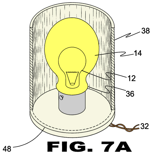 |
| FIGURE 7A Figure 7, is a detailed view of the present invention 10 showing how the fixtures are positioned within an existing plant container 26. The fixtures are preferably positioned so that the light shields 16 are spaced from the sidewall 38 of the container 26. This prevents or ensures that that the light shields 16 are not in contact with the sidewall 38 of the container 26. The plant container 26 plastic may not be heat resistant and may be melted by the heat generated by the light bulbs 12. It is envisioned that the bulbs 12 may be incandescent, florescent, light emitting diodes (LEDs), or any other suitable type of bulb 12. It is also envisioned that the present invention 10 may employ a string or strand of interconnected light sources that are protected by a sealed plastic tube or casing. These are some times referred to as rope lights. The rope light will not have light fixtures or anchors. The rope light will have a tube or casing having sealed ends and a plurality of light sources disposed therein. The light sources will be connected by a cord or wiring 32 inside the tube or casing. The cord or wiring 32 passes through the casing and has an end with a plug that is outside of the casing so that it can be connected to a household outlet. It is envisioned that the rope light may or may not employ a transformer 28. The rope light may employ a photo sensor 18, a control mechanism 44, and a connector 34. The connector 34 is, as previously discussed, waterproof and enables the user to install the rope light through the sidewall 38 of the plant container 26. The connector allows the user to make a smaller hole in the container 26. The hole will be only slightly larger than the outer diameter of the connector 34. It is envisioned that the connector 34 in the rope light will be outside the tube or casing and the rope light may employ a control mechanism 44 that is user programmable and may include a microprocessor. The base 22 and the light shield 16 of each fixtures are shown as being positioned above the soil level 40 in the container 26 since the fixtures are open are designed to be positioned above the soil level 40. Only the support 30 or anchor is intended to be buried in the soil. It is envisioned that the fixtures may be provided that are designed to be buried in the soil to make them less obtrusive (Figure 7A). They would employ a peripheral sidewall 38 and a closed bottom 48 with a light bulb 12 or light source disposed therein. A transparent lens 50 may close the open end of the fixture and prevent moisture and soil from entering. This would enable the fixture to be positioned so that the lens 50 is flush or nearly flush with the soil level 40. The lens 50 may be provided with a sealing means that is capable of providing a watertight seal between the lens 50 and the fixture. The lens 50 functions as a closure to protect the contents of the fixture. The lens 50 may be made from a transparent, or translucent material such as plastic or glass. It is also envisioned that the lens 50 may in corporate a color or tint in the same manner as the light globes 14 previously discussed. It is preferable that the lens 50 incorporates a transparent color so that colored light is emitted there from.
|
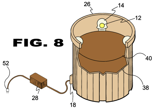 |
| FIGURE 8 Figures 8 and 9 are illustrative views of another embodiment of the present invention 10. In this embodiment, the container 26 has integral illuminable fixtures formed therein or secured thereon. The container 26 and its integral lighting system may include an photo sensor 18, a transformer 28, and a control mechanism 44 as with the previous embodiment. It is preferred that the photo sensor 18 is located on the exterior surface or sidewall 38 of the container 26 so that it is not affected by the light from the fixtures. In this embodiment the support 30 is an extension of the sidewall 38 and secures the light socket 20 to the sidewall 38 of the container 26. It is envisioned that the support 30 need not be formed in one piece with the container 26 but may be secured on the inner surface of the sidewall 38 of the container 26 with fasteners or adhesive. The container 26 may employ a single sidewall 38 or a double sidewall 38 (see Fig. 9). The use of a double sidewall 38 allows the wiring 32 to be disposed between the two walls so that it is protected from the soil and water that is inside the inner wall of the container 26. It is envisioned that this embodiment will employ light globes 14 to protect the light bulbs 12 or light sources. The globes 14 may be made in the same manner and have all the characteristics of the light globes 14 of the previous embodiment. The container 26 may be provided with reflective material 46 or reflective elements adjacent the light globes 14 to reflect and focus the light as needed. It is also envisioned that the light globes 14 of either embodiment may incorporate reflective material 46 located over a portion thereof. The reflective material 46 would preferably be located or disposed on the inner surface of the globe 14 but may be located on the outer surface in lieu or in addition to the inner surface. Having reflective material 46 on the light globes 14 eliminates the need for reflective material 46 on the container 26or the light shields 16.
|
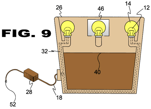 |
| FIGURE 9 Figures 8 and 9 are illustrative views of another embodiment of the present invention 10. In this embodiment, the container 26 has integral illuminable fixtures formed therein or secured thereon. The container 26 and its integral lighting system may include an photo sensor 18, a transformer 28, and a control mechanism 44 as with the previous embodiment. It is preferred that the photo sensor 18 is located on the exterior surface or sidewall 38 of the container 26 so that it is not affected by the light from the fixtures. In this embodiment the support 30 is an extension of the sidewall 38 and secures the light socket 20 to the sidewall 38 of the container 26. It is envisioned that the support 30 need not be formed in one piece with the container 26 but may be secured on the inner surface of the sidewall 38 of the container 26 with fasteners or adhesive. The container 26 may employ a single sidewall 38 or a double sidewall 38 (see Fig. 9). The use of a double sidewall 38 allows the wiring 32 to be disposed between the two walls so that it is protected from the soil and water that is inside the inner wall of the container 26. It is envisioned that this embodiment will employ light globes 14 to protect the light bulbs 12 or light sources. The globes 14 may be made in the same manner and have all the characteristics of the light globes 14 of the previous embodiment. The container 26 may be provided with reflective material 46 or reflective elements adjacent the light globes 14 to reflect and focus the light as needed. It is also envisioned that the light globes 14 of either embodiment may incorporate reflective material 46 located over a portion thereof. The reflective material 46 would preferably be located or disposed on the inner surface of the globe 14 but may be located on the outer surface in lieu or in addition to the inner surface. Having reflective material 46 on the light globes 14 eliminates the need for reflective material 46 on the container 26or the light shields 16.
|
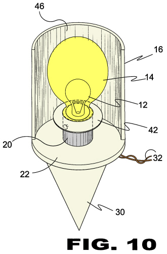 |
| FIGURE 10 Figure 10, is a front perspective view of a light unit of the present invention 10 with an additional element. Shown is a splashguard 42 of the present invention 10. The splashguard 42 may be employed with either embodiment of the present invention 10, i.e. where the lights are separate from the container 26 or where the lights are integral with the container 26. The splashguard 42 prevents splashing water from entering into the electrical connection between the bulb 12 and the socket 20 of the light fixture. The splashguard 42 may be an independent member installed between the bulb 12 and socket 20, it may be molded into the socket 20, it may be molded into the light globe 14, or it may be a separate piece secured on or around the light globe 14.
|
|