|
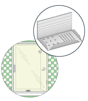
| FIGURE 1 FIGURE 1 shown is an illustrated view of the mountable soap dish 10 in use. The present invention provides a cantilevered soap dish 10 having a back wall support portion 12 that is mountable to a structure, using any means well known within the art, with a soap bar receptacle plate 14 angularly depending from the back wall support 12. The soap bar receptacle plate 14 has opposing side lips 16 with a front lip 18 extending therebetween. The front lip 18 provides for at least one water egress recess 22 for water to drain from the soap receptacle 11. As illustrated the soap dish 10 can be mounted for bath tub use or shower stall 20 use.
|
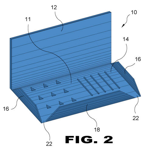 |
| FIGURE 2 FIGURE 2 is an illustrative view of the mountable soap dish 10. The present invention provides a cantilevered soap dish 10 having a back wall support portion 12 that is mountable to a structure, using any means well known within the art, with a soap bar receptacle plate 14 angularly depending from the back wall support 12. The soap bar receptacle 11 has opposing side lips 16 with a front lip 18 extending therebetween. The front lip 18 provides for at least one water egress recess 22 for water to drain from the soap receptacle portion.
|
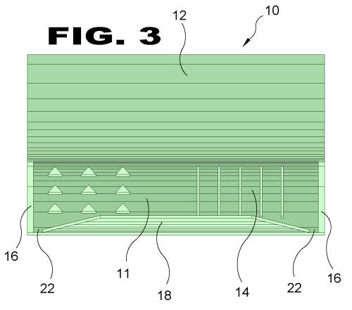 |
| FIGURE 3 FIGURE 3 is a front view of the mountable soap dish 10. The present invention provides a cantilevered soap dish 10 having a back wall support portion 12 that is mountable to a structure, using any means well known within the art, with a soap bar receptacle plate 14 angularly depending from the back wall support 12. The soap bar receptacle 11 has opposing side lips 16 with a front lip 18 extending therebetween. The front lip 18 provides for at least one water egress recess 22 for water to drain from the soap receptacle portion 14.
|
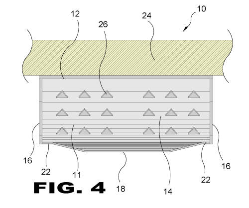 |
| FIGURE 4 FIGURE 4 is a top view of the mountable soap dish 10 in use. The present invention provides a cantilevered soap dish 10 having a back wall support portion 12 that is mountable to a structure, using any means well known within the art, with a soap bar receptacle plate 14 angularly depending from the back wall support 12. The soap bar receptacle 14 has opposing side lips 16 with a front lip 18 extending therebetween. The front lip 18 provides for at least one water egress recess 22 for water to drain from the soap receptacle 11. As illustrated the soap dish can be mounted on the wall 24 for bath tub use or shower stall use. Also provided a triangular protrusions 26 disposed on the top surface of the receptacle plate 14.
|
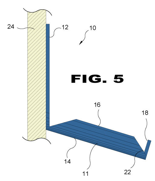 |
| FIGURE 5 FIGURE 5 is a side view of the present invention 10. The present invention provides a cantilevered soap dish having a back wall support portion 12 that is mountable to a structure 24, using any means well known within the art, with a soap bar receptacle plate 14 angularity depending from the back wall support 12. The soap bar receptacle 11 has opposing side lips 16 with a front side lip 18 extending therebetween. The front side lip 18 provides for at least one water egress recess 22 for water to drain from the soap receptacle 11. As illustrated the soap dish can be mounted to the wall 24 for bath tub use or shower stall use.
|
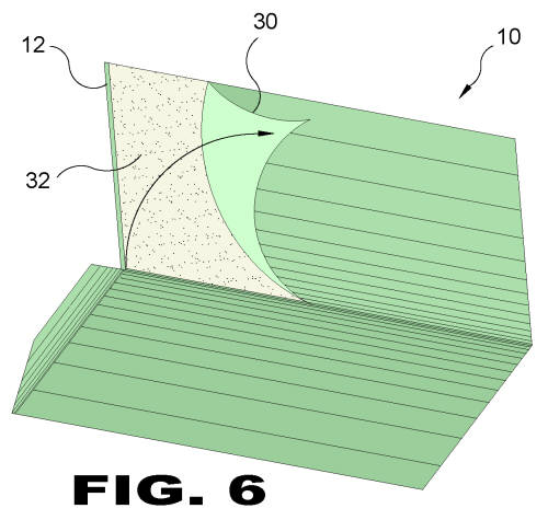 |
| FIGURE 6 FIGURE 6 is a back view of the present invention 10. The present invention provides a mountable cantilevered soap dish 10 having a back wall support 12 that is mountable to a structure, using any means well known within the art. Shown is a mounting method wherein the rear portion of the back wall support 12 has a peel off backing 30 that when removed exposes an adhesive element 32 for mounting to a wall structure.
|
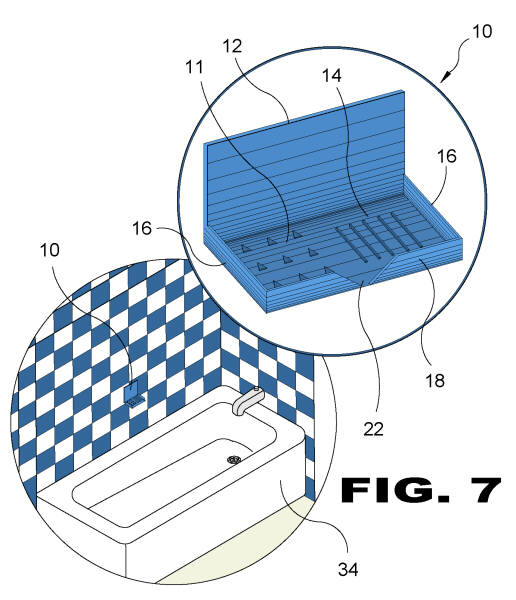 |
| FIGURE 7 FIGURE 7 shown is an illustrated view of the mountable soap dish 10 in use. The present invention provides a cantilevered soap dish 10 having a back wall support portion 12 that is mountable to a structure, using any means well known within the art, with a soap bar receptacle plate 14 angularly depending from the back wall support 12. The soap bar receptacle plate 14 has opposing side lips 16 with a front lip 18 extending therebetween. The front lip 18 provides for at least one water egress recess 22 for water to drain from the soap receptacle 11. As illustrated the soap dish 10 can be mounted for bath tub 34 use.
|
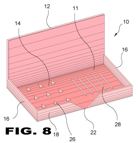 |
| FIGURE 8 FIGURE 8 is an illustrative view of the mountable soap dish 10. The present invention provides a cantilevered soap dish 10 having a back wall support portion 12 that is mountable to a structure, using any means well known within the art, with a soap bar receptacle plate 14 angularly depending from the back wall support 12. The soap bar receptacle 11 has opposing side lips 16 with a front lip 18 extending therebetween. The front lip 18 provides for at least one water egress recess 22 for water to drain from the soap receptacle portion. Furthermore, triangular protrusions 26 and linear protrusions 28 are provided on the top surface of the receptacle plate 14.
|