*****New Product For Licensing, Manufacturing, and/or Investors*****
As attorney for the inventor of the innovative Universal Lug Wrench we are currently seeking manufacturing companies to license, purchase patent rights or enter into a royalty agreement for this timely invention.
Objects of the present invention:
- to provide a universal lug wrench
- to provide a universal lug wrench that can be used by ordinary people to loosen and fasten the lug nuts on automobile tires without undue strain on the users part
- to provide a universal lug wrench including a supporting adjustment stand and a long arm
- to provide a universal lug wrench that is easy to disassemble and store
- to provide a universal lug wrench with various interchangeable sockets for different sized lug nuts
- to provide a universal lug wrench with an extension for the sockets that are inserted into the adjustable clamp providing a pivoting point for the wrench
The following pictures are meant to display possible physical characteristics of the present invention and are not to be taken in a limiting sense. It is understood that other embodiments may be utilized and that structural changes may be made without departing from the scope of the invention.
| LIST OF REFERENCE NUMERALS |
| 10 present invention |
38 axis |
| 12 lug nut | 40 prior art wrench |
| 14 tire |
42 arm end point |
| 16 adjustable stand | 44 arm end point |
| 18 arm |
48 axis |
| 20 wrench | 50 point of torque |
| 21 handle |
52 length of arm |
| 22 socket | 54 extension |
| 23 extra socket |
56 clamp |
| 24 prior art wrench | 57 clamp aperture |
| 25 elbow |
58 head |
| 26 point | 60 rod |
| 28 short arm axis |
62 release lever |
| 30 end point | 64 base |
| 32 handle |
66 oil hole |
| 34 length of leverage | 68 connector sleeve |
| 36 length of short arm |
|
|
| PATENT DRAWINGS |
 |
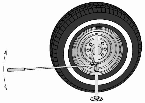
| FIGURE 1 Figure 1 is a perspective view of the present invention in use. |
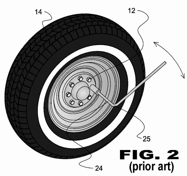 |
| FIGURE 2 Figure 2 is a view of a prior art wrench in use.
|
 |
| FIGURE 3 Figure 3 is a diagram of the torques acting on the wrench shown in Figure 2. |
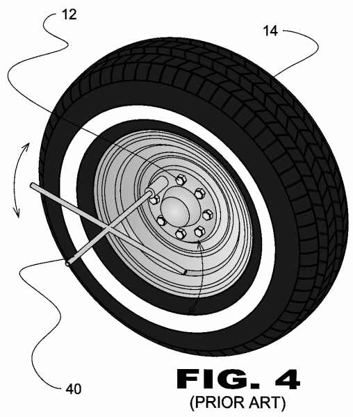 |
| FIGURE 4 Figure 4 is a view of another prior art wrench in use. |
 |
| FIGURE 5 Figure 5 is a diagram showing the torque acting on the wrench shown in Figure 4. |
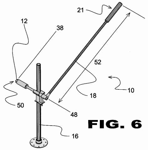 |
| FIGURE 6 Figure 6 is a diagram showing the torque applying action on the current invention. |
 |
| FIGURE 7 Figure 7 is an exploded view of the current invention. |
 |
| FIGURE 8 Figure 8 is a view showing various parts of the current invention. |
 |
| FIGURE 9 Figure 9 is a view of the adjustable stand with a clamp relocatable along the pipe. |
 |
| FIGURE 10 Figure 10 is a view of the adjustable clamp parts. |
 |
| FIGURE 11 Figure 11 is a view of the present invention on a lug nut in a different location showing a readjusted position of the clamp on the stand. |
|
If you are interested in licensing, purchasing the rights to the above invention or entering into a royalty
agreement please contact the office of Michael I. Kroll as follows:
Michael I. Kroll
80 Skyline Drive, Suite 304
Plainview, New York 11803
Tel. #: 800-367-7774
Tel. #: 516-367-7777
Fax #: 800-367-7999
Fax #: 516-802-0510