Water Desalination & Filtration System & Process

*****New Product For Sale, Licensing and/or Investors*****

The following patent is currently for sale by the inventor. If you are interested in making an offer or would like more information please contact the attorney at the numbers listed on the bottom of this page.


U.S. Patent : # 7,608,171

Inventor : Samuel Okwaja Otukol

invention uses
patent drawings
contact info
patent attorney

patent drawing


Highlights of the Invention

This invention, involving water desalination or purification, is different from the current three methods available today. The current methods; reverse osmosis, electrodialysis and distillation have numerous limitations, which hinder large-scale usage of ocean or sea water.

The key features of the present invention are:

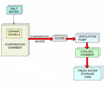
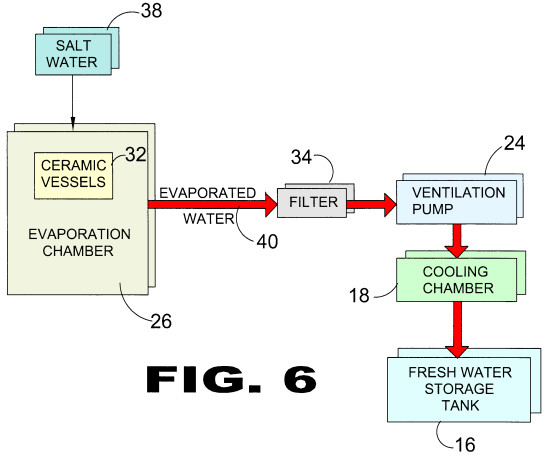
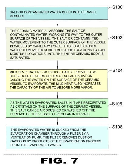
  1. Salty or contaminated water is evaporated at low temperatures, thus requiring less energy to do the job.

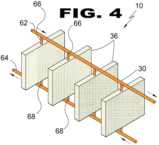
  2. The medium for providing an opportunity for evaporation (bisque fired clay) is readily available and inexpensive.

  3. The amount of water evaporated depends on the surface area provided to cause the evaporation therefore the method becomes more efficient as surface area is expanded. The only limiting factor to expanding surface area is the amount of building space available for the job.

  4. In warm climates evaporation can be achieved through direct solar heating and little or no energy is required to achieve it.

  5. Evaporation can occur 24 hours a day, 7 days a week without interruption.

  6. The process emulates the way nature purifies water.

  7. An evaporation facility can be built anywhere in the world where salt water exists and fresh water is in short supply.

  8. The process does not need expensive technology to achieve success.

As attorney for the inventor of the innovative new Water Filtration System and Process we are currently seeking manufacturing companies to license, purchase patent rights or enter into a royalty agreement for this timely invention. Interested parties can reach the attorney at the contact numbers listed at the bottom of this page.

The following pictures are meant to display possible physical characteristics of the present invention and are not to be taken in a limiting sense. It is understood that other embodiments may be utilized and that structural changes may be made without departing from the scope of the invention.


LIST OF REFERENCE NUMERALS
10 present invention 46 fresh water pipe
12 cold water tank48 first salt water pipe
14 salt water tank 50 second salt water pipe
16 fresh water tank52 salt water tank top
18 condensation chamber 54 salt water tank bottom
20 condensation surface pipes56 salt water tank side
22 return duct 58 fresh water
24 ventilation pump60 air extraction pump
26 evaporation chamber 62 first end salt water pipe
28 windows64 second end salt water pipe
30 copper tubing 66 first exposed end of tubing
32 vessel68 second embedded end of tubing
34 filter 70 first connection point on second salt water pipe
36 panels72 second connection point on second salt water pipe
38 salt water 74 condensation structure
40 evaporated water76 cold water inflow pipe
42 inflow directional arrow 78 cold water outflow pipe
44 outflow directional arrow

PATENT DRAWINGS
patent drawing
FIGURE 1

Figure 1 is an illustrative view of the desalination process of the present invention.

patent drawing
FIGURE 2

Figure 2 is an illustrative view of the desalination process of the present invention.

patent drawing
FIGURE 3

Figure 3 is an additional vessel configuration of the desalination process.

patent drawing
FIGURE 4

Figure 4 is another additional vessel configuration of the desalination process.

patent drawing
FIGURE 5

Figure 5 is another additional vessel configuration of the desalination process.

patent drawing
FIGURE 6

Figure 6 is a block diagram of the desalination process.

patent drawing
FIGURE 7

Figure 7 is a flow diagram of the desalination process.

patent drawing
FIGURE 8

Figure 8 is a continuation of the flow diagram of Figure 7 of the desalination process.

patent drawing
FIGURE 9

Figure 9 is a logic diagram of the desalination process.

patent drawing
FIGURE 10

Figure 10 is a perspective view of a tubing lattice condensation of the desalination process of the present invention.

If you are interested in licensing, purchasing the rights to the above invention or entering into a royalty agreement please contact the office of Michael I. Kroll as follows:

Michael I. Kroll
80 Skyline Drive, Suite 304
Plainview, New York 11803
Tel. #: 800-367-7774
Tel. #: 516-367-7777
Fax #: 800-367-7999
Fax #: 516-802-0510
E-Mail patent@invention.net

patent attorney home page