 |
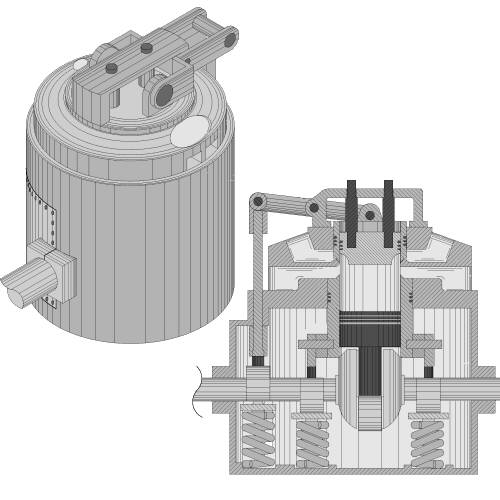
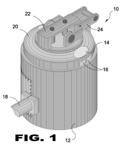
| FIGURE 1 FIGURE 1 is a perspective view of the present invention 10. Shown is the present invention 10 having a lower housing 12 with a compact design that can be manufactured to any size accordingly. Additionally shown is the present invention having multiple inlets 14 and outlets 16 for intake and exhaust stages so that multiple steam sources may be combined into the device if desired. Also shown is the crank shaft 18 and the relation ship of the upper manifold 20 with the structural bridge 22 and the lever arm 24.
|
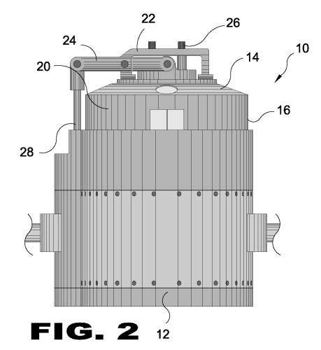 |
| FIGURE 2 FIGURE 2 is a side view of the present invention 10. Shown is the side profile of the present invention showing how the present invention has a substantially cylindrical shape and compact design. Shown are the lower housing 12 and upper manifold 20 with intake 14 and outlet 16 ports. Also shown are the structural bridge 22, retaining pin 26, lever arm 24 and the push rod 28.
|
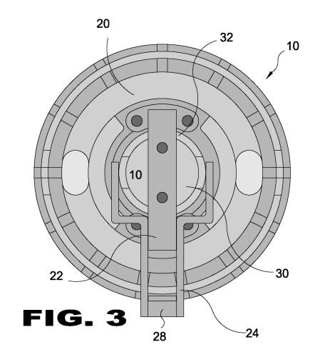 |
| FIGURE 3 FIGURE 3 is a top view of the present invention 10. Shown is the top of the present invention having a structural bridge 22 and two retaining pins 26 for supporting a central retainer 30, and also to serve as a fulcrum for the lever arms 24 attached to the push rod 28. This structural bridge is fixed to the upper manifold 20 and allows for the lowering and raising of the upper sealing gate 32 in cooperation with the pivotal functioning of the lever arm.
|
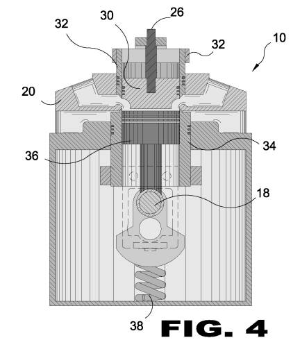 |
| FIGURE 4 FIGURE 4 is a sectional view of the present invention 10. Shown is the internal components of the present invention and how they relate to one another. The upper 32 and lower 34 sealing gates are connected to lever arms and cam systems with springs 38 in order to move up or down when needed during a cycle. The lower sealing gate 34 moves about in relation in-between a crank shaft 18 supported piston 36 held inside while the upper manifold 20 and cam linkages retain the outsides. For the upper sealing gate a retention pin 26 and structural bridge 22 provide support for a central retainer 30 to support the inside portions of the upper lift gate, along with an opening in the top of the upper manifold 20 for supporting the outsides of the upper lift gate.
|
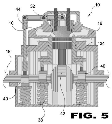 |
| FIGURE 5 FIGURE 5 is an illustrative view of the present invention 10 during the intake phase. Shown is the steam engine turbine of the present invention utilized in the conversion of a high pressure steam source into rotative mechanical torque in a highly efficient manner. The device utilizes two primary stages with the system having an optimum intake stage that translates into an optimum release or exhaust stage respectively. As the upper sealing gate 32 raises due to the lever arm 24 responding to the push rod 44 and opening the intake port 14, the lower sealing gate 34 also rises due to cams 40 and springs 38, along with it in order to seal the exhaust or outlet ports 16 simultaneously. The piston rod 42 serves to rotate the crank shaft 18 and associated cams 40.
|
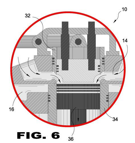 |
| FIGURE 6 FIGURE 6 is a detailed sectional view of the present invention 10. Shown is a detailed view of the present invention depicting that when the piston 36 is at top dead center the upper sealing gate 32 and intake port 14 is fully open while the lower sealing gate 34 and exhaust port 16 is closed. Coming from a high pressure source this is equivalent to an intake or ignition stroke for a two cycle engine design. This stage creates downward force on the piston 36 forcing it to make a power stroke.
|
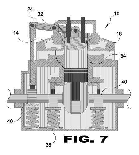 |
| FIGURE 7 FIGURE 7 is a sectional illustrative view of the present invention 10 in the exhaust phase. Shown is the present invention comprising a steam engine turbine utilized in the conversion of a high pressure steam source into rotative mechanical torque. The device utilizes two primary stages having an optimum intake stage that translates into an optimum release or exhaust stage respectively. As the upper sealing gate 32 lowers it closes the intake 14 due to the lever arm 24 while the lower sealing gate 34 also lowers due to a plurality of cams 40 and springs 38 in order to open the exhaust or outlet ports 16 simultaneously.
|
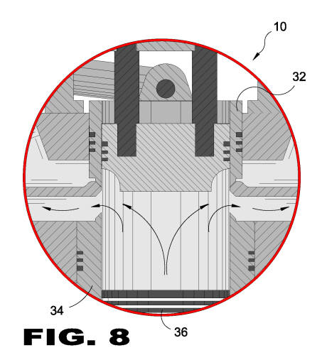 |
| FIGURE 8 FIGURE 8 is a detailed sectional view of the present invention 10. Shown is a detailed view of the present invention depicting that when the piston 36 is in the bottom position the upper sealing gate 32 is fully closed while the lower sealing gate 34 is opened. Coming from a high pressure source this is equivalent to exhaust or outlet stroke for a two cycle engine design. This stage relieves pressure and helps return the piston back to the top position using momentive force.
|