 |
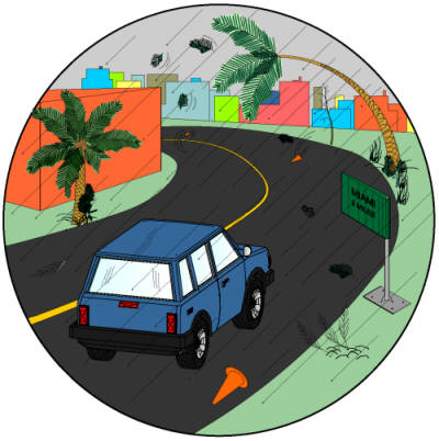
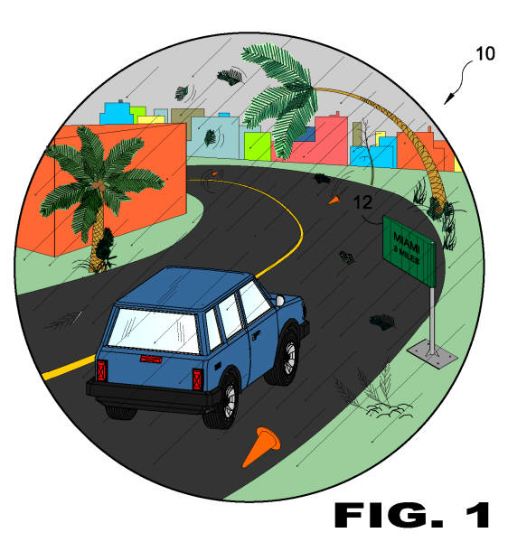
| FIGURE 1 FIGURE 1 is an illustrative view of the present invention 10 in use. The present invention is a wind resistant highway sign system 10 that responds to wind shear better than conventional signs by moving a storm sign 12 on a set spring like a flag moves in the wind, and will unlock the storm sign 12 at a predetermined wind speed, lifting the storm sign 12 on its springs until the wind reduces and then returns the sign 12 to its normal position.
|
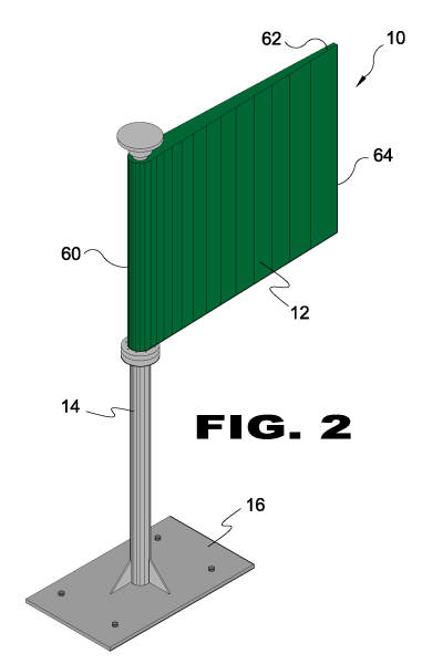 |
| FIGURE 2 FIGURE 2 is a perspective view of the present invention 10. Shown is the storm sign 12 pivotally mounted on a sign support post 14 secured to the ground by a base 16. The sign 12 has a thick pivoting end 60 that tapers to a thinner distal end 62 with an aerodynamic edge 64.
|
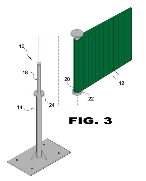 |
| FIGURE 3 FIGURE 3 is a perspective view of the storm sign 12 of the present invention 10. The sign support 14 has a sign support post 18 extending linearly therefrom that is insertable into a throughbore in the sign post 20 of the storm sign 12. The sign 12 has a sign post 20 with a collar 22 that is seated on an opposing sign support collar 24 when the sign support post 18 is inserted into the sign post 20.
|
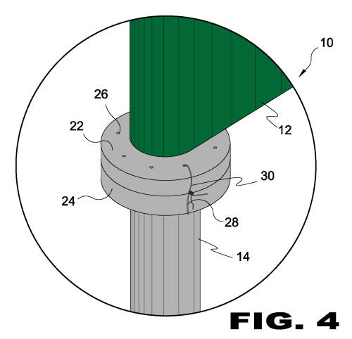 |
| FIGURE 4 FIGURE 4 is a detailed view of the present invention 10. Shown is the sign post collar 22 seated and selectively positioned on the sign support collar 24 with each collar having a plurality of corresponding recesses 26. A frangible locking element 28, illustrated here as a wire 30 to maintain the static relationship between the sign 12 and the sign support 14 when windspeed remains below the preselected threshold.
|
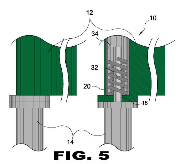 |
| FIGURE 5 FIGURE 5 is a sectional side view of the present invention 10. Shown is the sign 12 rotationally moveable on a set spring 32 coiled around the sign support post 18 within the sign post throughbore 34 sign post 20 that will unlock the sign 12 at a predetermined windspeed, lifting the sign 12 on its spring 32 until the wind reduces and then returns the sign 12 to its normal position relative to the sign support 14.
|
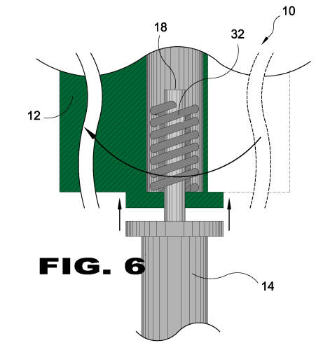 |
| FIGURE 6 FIGURE 6 is a side sectional view of the present invention 10. Shown is the sign 12 released due to excessive windspeed and rotating axially around the sign support post 18 to compress the spring 32 and apply rotational and downward forces to return the sign 12 to its original position relative to the sign support once the windspeed subsides to within the preselected user parameters.
|
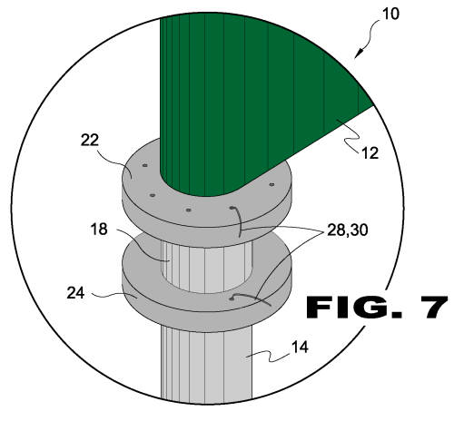 |
| FIGURE 7 FIGURE 7 is a detailed view of the present invention 10 in excessive windspeed conditions. Excessive windspeed pressure has been applied to the sign 12 according to the preselected parameters and compromised the wire 30 serving as a frangible locking element 28 retaining the sign post collar 22 to the sign support collar 24 to enable the sign 12 to rotate axially on the sign support post 18 of the sign support 14.
|
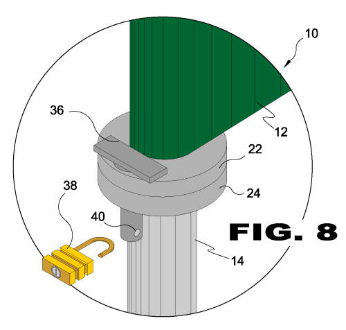 |
| FIGURE 8 FIGURE 8 is a detailed view of the present invention 10 having an additional locking element. Shown is the sign post collar 22 and sign support collar 24 having mating collar recesses 26 for receiving a bolt lock 36 having a bolt lock aperture 40 to accept a padlock 38 to allow for manually enabling the rotation of the sign 12 relative to the sign support 14 by authorized personnel.
|
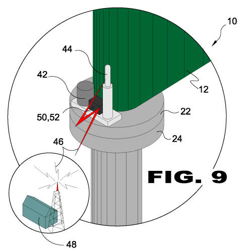 |
| FIGURE 9 FIGURE 9 is a detailed view of the present invention 10 with an automated locking device. Shown is the sign post collar 22 and the sign support collar 22 secured with a motorized bolt lock 42 having a receiver 44 to receive a signal 46 from a remote station 48 to release the sign 12 from the static position. An on board computer control device 50 such as an anemometer 52 may be utilized to determine when the sign 12 should or should not be locked.
|
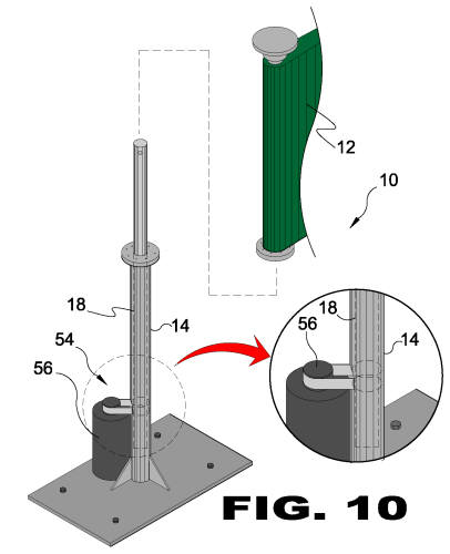 |
| FIGURE 10 FIGURE 10 is a perspective view of the present invention 10 having a motorized return mechanism. 54 wherein the sign support post 18 extends through the sign support 14 and is rotated by a return motor 56 to return large signs 58 to the position of origin in cases when the large sign 58 is too heavy to be returned back into place solely utilizing a spring based mechanism.
|
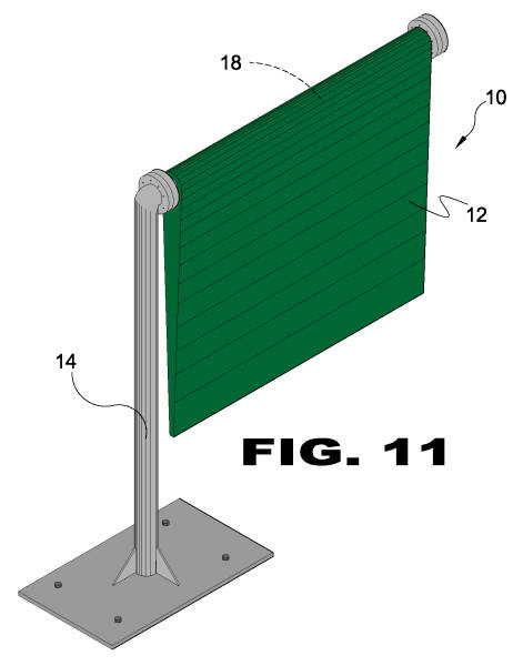 |
| FIGURE 11 FIGURE 11 is an additional element of the present invention. The sign 12 extends downward from a horizontal support post 18 projecting perpendicularly from a vertical sign support 14.
|