*****New Product For Sale, Licensing and/or Investors*****
The following patent is currently for sale by the inventor. If you are interested in making an offer or would like more information please contact the attorney at the numbers listed on the bottom of this page.
U.S. Patent : # 7,290,815
Click patent number for full text patent document.
As attorney for the inventor of the innovative new Improved Hoist Sling we are currently seeking manufacturing companies to license, purchase patent rights or enter into a royalty agreement for this timely invention. Interested parties can reach the attorney at the contact numbers listed at the bottom of this page.
Objects of the present invention:
to provide a means and apparatus to move a load of palletized material safely
to provide a hoist sling having a pair of blades each with a terminal end cavity and a channel extending to the tip of the blade
to provide a hoist sling having load bearing members releasably fastenable to the blades
to provide a hoist sling having load bearing members with a puck-like lifting lug fastened thereto
to provide a hoist sling having a load bearing member support frame with means for retaining one end of a load bearing member
to provide a hoist sling having load bearing members converging on a hoist sling attachment serving as terminus to the load bearing members
The following pictures are meant to display possible physical characteristics of the present invention and are not to be taken in a limiting sense. It is understood that other embodiments may be utilized and that structural changes may be made without departing from the scope of the invention.
LIST OF REFERENCE NUMERALS
10 present invention
30 lifting lug
12 first pallet lift skid
32 aperture
14 second pallet lift skid
34 ring
16 channel
36 disk
18 cavity
38 apertures
20 load bearing member
40 eyelet
22 spreader frame
42 anchor line engaging member
24 anchor line
44 pivot
26 lifting ring
46 link
28 pallet
PATENT DRAWINGS
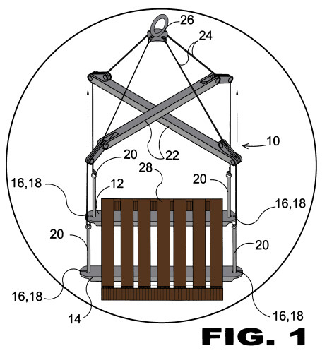
FIGURE 1
Figure 1 is an illustrative view of the present invention in use.
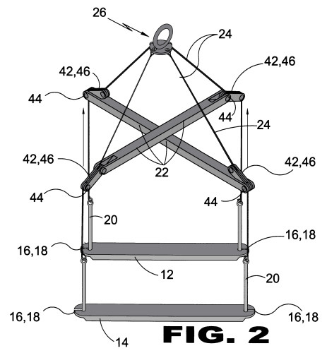
FIGURE 2
Figure 2 is a perspective view of the present invention fully assembled.
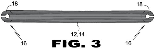
FIGURE 3
Figure 3 is a top view of the invention's pallet lift skid.
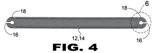
FIGURE 4
Figure 4 is a bottom view of the invention's pallet lift skid.
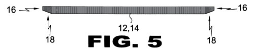
FIGURE 5
Figure 5 is a side view of the invention's pallet lift skid.
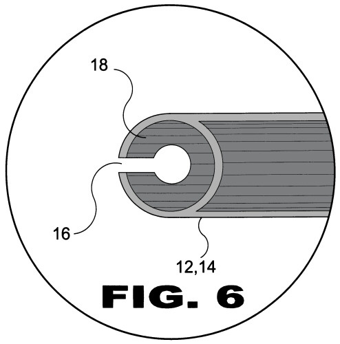
FIGURE 6
Figure 6 is a detail view of the invention's pallet lift skid end portion.
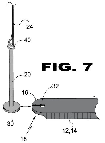
FIGURE 7
Figure 7 is a detail view of the invention's pallet lift skid (end portion) and lifting lug (not connected).
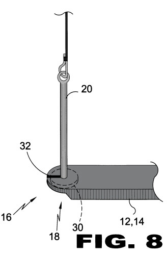
FIGURE 8
Figure 8 is a detail view of the present invention's pallet lift skid (end portion) and lifting lug (connected).
FIGURE 9
Figure 9 is a top and side view of the invention's lifting ring.
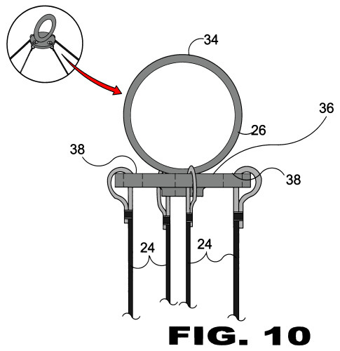
FIGURE 10
Figure 10 is a side view of the present invention's lifting ring.
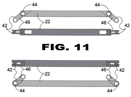
FIGURE 11
Figure 11 is a top and side view of the invention's diagonal spreader bars.