 |
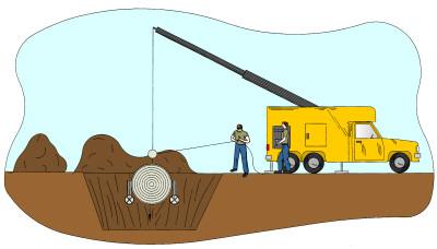
| FIGURE 1 Figure 1 is a perspective view of the present invention in use. Shown is an excavation site where a crane is being used to place an underground tank having the lightweight ballast forms attached thereto. |
 |
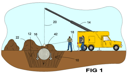
| FIGURE 1A Figure 1A is a perspective view of the present invention in use. Shown is an excavation site where an underground tank and lightweight ballast forms have been installed into an excavation which has been backfilled and a pump hose has been attached to one of the stacks of the lightweight ballast forms for the purpose of filling the form with an appropriate material such as concrete. |
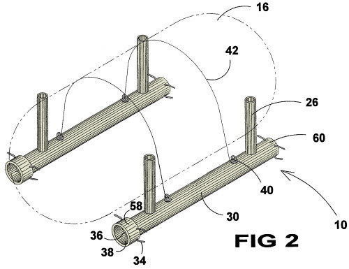 |
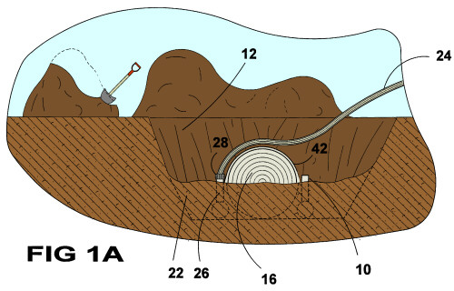
| FIGURE 2 Figure 2 is an illustration of the present invention attached to an underground tank shown in outline. The lightweight ballast form is comprised of a cylindrical member having stack-like members forming an integral unit providing means for inserting a suitable ballast material, such as concrete, into one stack member as air is displaced out the other stack-like member. Also shown are lengths of rebar which are used to hold pieces of steel tek acting as means for the lightweight ballast form distal ends. |
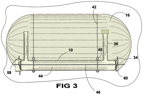 |
| FIGURE 3 Figure 3 is a cross section of the present invention, taken from Fig 2 as indicated. Shown is the cavity of the lightweight ballast form having a length of rebar positioned therein and having two stack-like members providing means for pumping an appropriate ballast material into one stack-like member as air is displaced out through the other member. Also shown are short lengths of rebar installed through each distal end to hold a capping material, such as steek tek, in place. Also shown is the anchoring means for holding the cable between the lightweight ballast forms. |
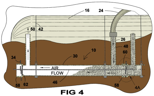 |
| FIGURE 4 Figure 4 is a diagrammatic view of the present invention having a pump hose connected to one of the stack-like members having concrete pumped into the lightweight ballast form as air is being displaced out the other stack-like member. Also shown are short lengths of rebar installed through each distal end holding a capping material, such as steek tek, in place. |
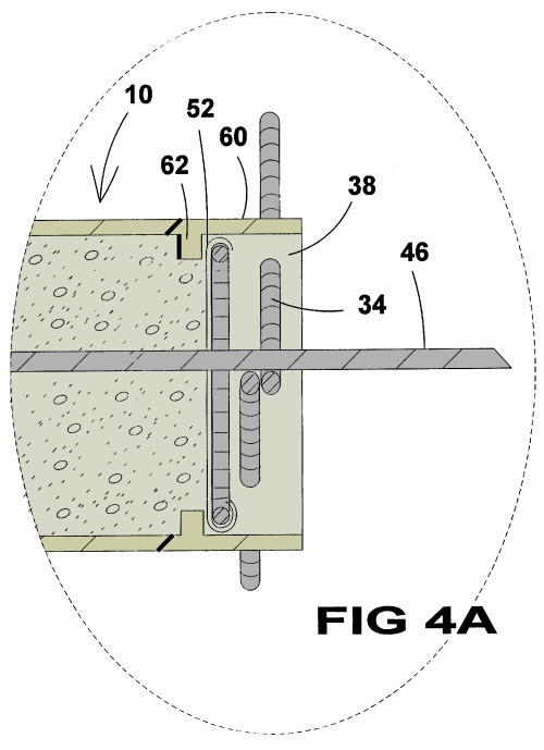 |
| FIGURE 4A Figure 4A is an enlarged view, taken from Fig 4, as indicated. Shown is one means of capping the distal ends of the lightweight ballast form wherein a piece of steel tek has been cut to fit the opening and placed inside the distal end of the form and pieces of rebar are inserted through the pipe holding a capping material in place. |
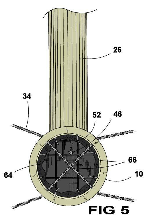 |
| FIGURE 5 Figure 5 is an end view of the present invention, taken from Fig 4, as indicated. Shown is a material, such as steel tek, cut to size and inserted into the distal end of the lightweight ballast form performing closure of the distal ends of the form as well as providing support for reinforcement rods inserted lengthwise through the lightweight ballast form. Also shown is one means of maintaining the positioning of the capping material by placing reinforcement rods through the structure of the lightweight ballast form. |
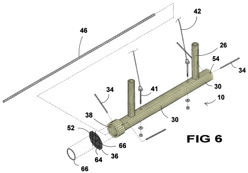 |
| FIGURE 6 Figure 6 is an exploded view of the component of the preferred embodiment of the present invention. Shown is the lightweight ballast form being a basically cylindrical tube having stack-like members providing means for access the cavity of the ballast form wherein will be pumped an appropriate material such as concrete after the tank and form are placed in an excavation. Also shown are anchoring pins used to attach the belting material from one ballast member to the other. Also shown are means of closure for the distal ends of the ballast form which may be comprised of steel tek, a tar like paper material woven over a metal frame, which is cut to size and inserted into the open ends of the ballast form and held in place by a number of pieces of rebar which is inserted through apertures in the structure ends of the ballast form. |
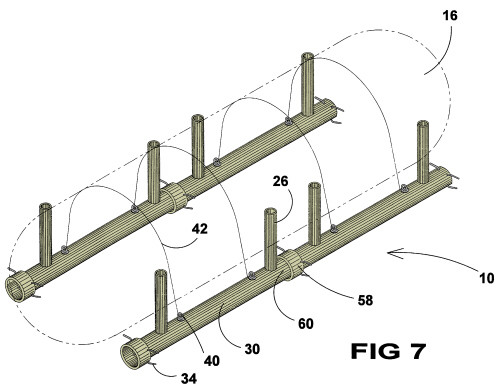 |
| FIGURE 7 Figure 7 is a perspective view of an alternate configuration of the preferred embodiment of the present invention attached to an underground tank, shown in outline wherein two of the lightweight ballast forms are joined together by appropriate means, such as glueing. The lightweight ballast form is comprised of a cylindrical member having stack-like members forming an integral part thereof providing means for inserting a suitable ballast material, such as concrete, therein. Also shown are lengths of rebar which are used to hold pieces of steel tek acting as means of closure for the lightweight ballast form distal ends. |
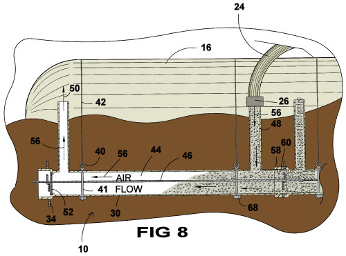 |
| FIGURE 8 Figure 8 is a diagrammatic view of the present invention having a pump hose connected to one of the stack-like members having conrete pumped into the lighweight ballast form as air is being displaced out of the other stack-like member. Shown is the cavity of the joined lightweight ballast forms having a length of rebar positioned therein and each having two stack-like members providing means for pumping an appropriate ballast material into one stack-like member as air is displaced out through the other member. Also shown are short lengths of rebar installed through each distal end to hold a capping material, such as steel tek, in place, and short lengths of rebar installed through the joining ends of the lightweight ballast forms. Also shown is the anchoring means for holding the cable between the lightweight ballast forms. |