| Self Packing Non-Leak Hose Storage System |
*****New Product For Sale or Licensing*****
| The following patent is currently for sale or license by the inventor. If you are interested in making an offer or would like more information please contact the attorney at the numbers listed on the bottom of this page. |
As attorney for the inventor of the innovative new Self Packing Non-Leak Hose Storage System we are currently seeking investors and manufacturing companies to license, purchase patent rights or enter into a royalty agreement for this timely invention. Interested parties can reach the attorney at the contact numbers listed at the bottom of this page.
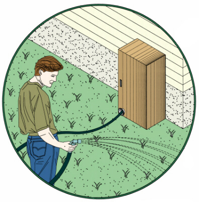
The present invention relates to hose reels, and more specifically, to a storage device for a hose that allows a user to selectively pull a hose out to a desired length and automatically have that length returned to storage utilizing potential energy stored within a block and tackle mechanism that is charged by the pulling of the hose out of the device.
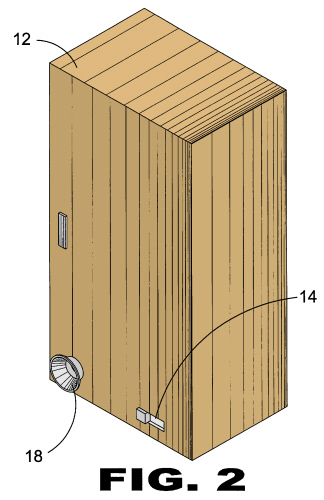
In the fully retracted position the hose is wound around a plurality of upper and lower hose guides. The guides have a plurality of rollers set apart holding the hose in an oval like configuration. When the hose is withdrawn potential energy is stored in a block and tackle device until selective release whereupon stored potential energy is exerted retracting the hose back to its original oval like winding.
|
Objects of the present invention:
- to provide an apparatus for dispensing and retrieving a length of hose
- to provide a storage device for a hose having a system whereby a user can selectively pull a hose out to a desired length and selectively rewind back into the storage device
- to provide an apparatus for a hose using a spring and block and tackle for storing potential energy
- to provide an apparatus for a hose wherein a block and tackle mechanism is charged by pulling the hose out of the storage device
|
The following pictures are meant to display possible physical characteristics of the present invention and are not to be taken in a limiting sense. It is understood that other embodiments may be utilized and that structural changes may be made without departing from the scope of the invention.
| LIST OF REFERENCE NUMERALS |
| 10 present invention |
40 guide wheel |
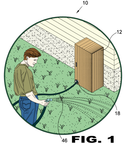
| 12 housing |
42 guide track |
| 14 release mechanism |
44 guide wheel shaft |
| 16 linkage |
46 hose |
| 18 hose port |
48 spring |
| 20 upper roller guides |
50 brace |
| 22 lower roller guides |
52 cross bar |
| 24 brake drum |
54 roller |
| 26 ratchet mechanism |
56 tooth |
| 28 block and tackle |
58 fixing plate |
| 30 upper pulleys |
60 through hole |
| 32 fixed shaft |
62 nipple |
| 34 lower pulley |
64 lifting bar |
| 36 moving shaft |
66 lower extension |
| 38 cable |
|
|
| PATENT DRAWINGS |
 |
| FIGURE 1 Figure 1 is an illustrative view of the present invention in use. |
 |
| FIGURE 2 Figure 2 is a perspective view of the present invention. |
 |
| FIGURE 3 Figure 3 is a perspective view of the internal components of the present invention. |
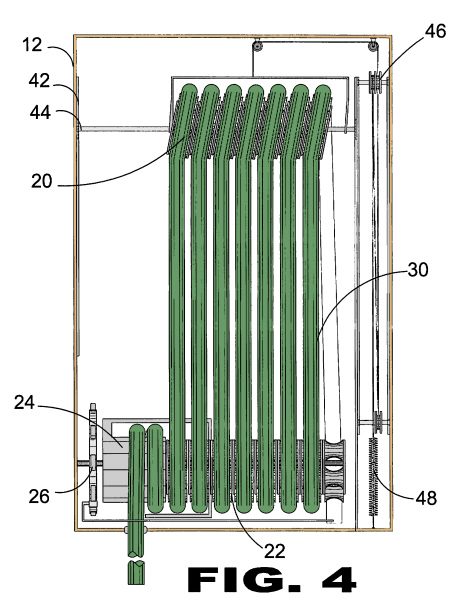 |
| FIGURE 4 Figure 4 is a front view of the internal components of the invention in the wound position. |
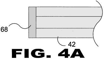 |
| FIGURE 4A Figure 4A is a perspective view of an end cap on a guide track of the present invention. |
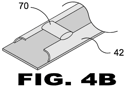 |
| FIGURE 4B Figure 4B is a perspective view of a stop on a guide track of the present invention. |
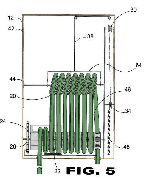 |
| FIGURE 5 Figure 5 is a front view of the internal components of the present invention in the unwound position. |
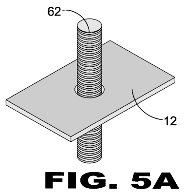 |
| FIGURE 5A Figure 5A is a perspective view of the nipple of the present invention. |
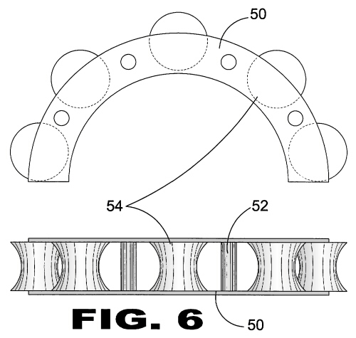 |
| FIGURE 6 Figure 6 is a top and side view of the bottom hose guide of the present invention. |
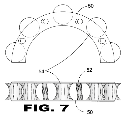 |
| FIGURE 7 Figure 7 is a top and side view of the top hose guide of the present invention. |
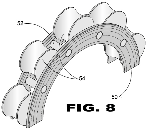 |
| FIGURE 8 Figure 8 is a perspective view of the bottom hose guide of the present invention. |
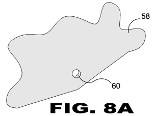 |
| FIGURE 8A Figure 8A is a perspective view of a fixing plate of the present invention. |
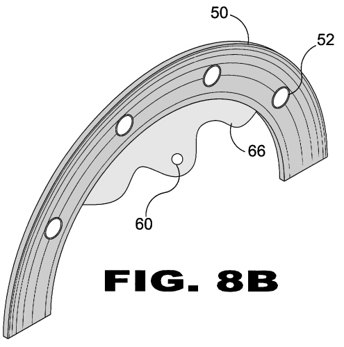 |
| FIGURE 8B Figure 8B is a perspective view of a modified brace of the present invention. |
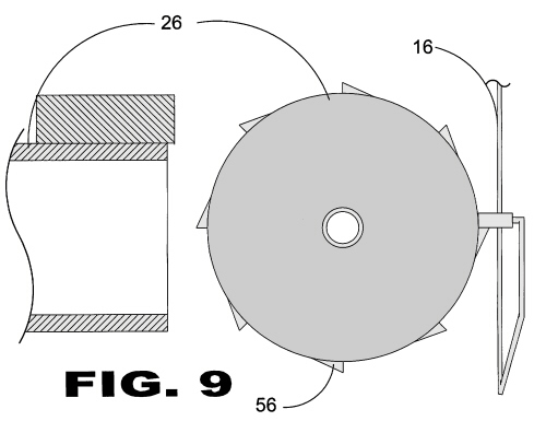 |
| FIGURE 9 Figure 9 is a perspective view of the ratchet mechanism of the present invention. |
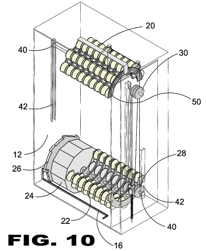 |
| FIGURE 10 Figure 10 is a perspective view of the internal components of the present invention. |
|
If you are interested in licensing, purchasing the rights to the above invention or entering into a royalty
agreement please contact the office of Michael I. Kroll as follows:
Michael I. Kroll
80 Skyline Drive, Suite 304
Plainview, New York 11803
Tel. #: 800-367-7774
Tel. #: 516-367-7777
Fax #: 800-367-7999
Fax #: 516-802-0510