| PATENT DRAWINGS | |||||||||||||||||||||||||||||||||||||||||||||||||||||
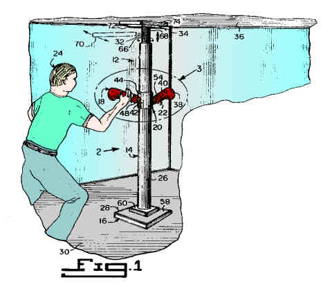 |
FIGURE 1 Figure 1 is a perspective view showing a martial artist using a first embodiment of the instant invention in a room. |
||||||||||||||||||||||||||||||||||||||||||||||||||||
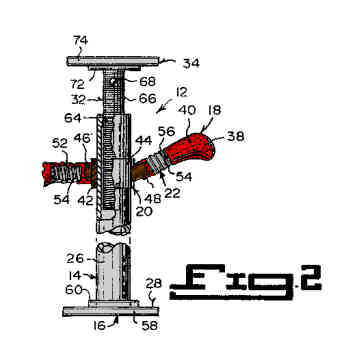 |
FIGURE 2 Figure 2 is an elevational view of the first embodiment taken in the direction of arrow 2 in figure 1. |
||||||||||||||||||||||||||||||||||||||||||||||||||||
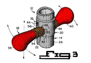 |
FIGURE 3 Figure 3 is an enlarged perspective view of the area indicated by arrow 3 in figure1. |
||||||||||||||||||||||||||||||||||||||||||||||||||||
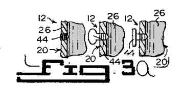 |
FIGURE 3a Figure 3a are enlarged cross sectional views as indicated by arrow 3a in figure 3 showing different types of setscrews. |
||||||||||||||||||||||||||||||||||||||||||||||||||||
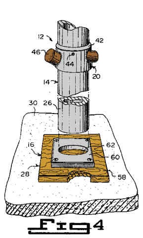 |
FIGURE 4 Figure 4 is a partly exploded perspective view of a portion of the first embodiment with parts broken away and in section. |
||||||||||||||||||||||||||||||||||||||||||||||||||||
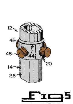 |
FIGURE 5 Figure 5 is a perspective view of the first embodiment, showing a second stud configuration on the height adjustable collar. |
||||||||||||||||||||||||||||||||||||||||||||||||||||
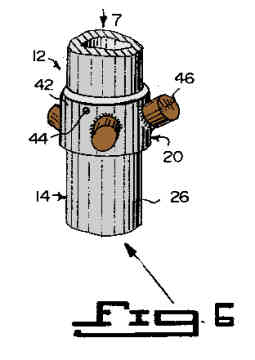 |
FIGURE 6 Figure 6 is a perspective view similar to figure 5, showing a third stud configuration on the height adjustable collar. |
||||||||||||||||||||||||||||||||||||||||||||||||||||
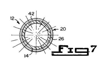 |
FIGURE 7 Figure 7 is a diagrammatic top view taken in the direction of arrow 7 in figure 6, showing various radial positions for the studs on the height adjustable collar. |
||||||||||||||||||||||||||||||||||||||||||||||||||||
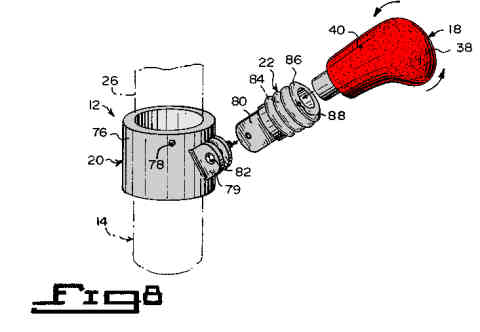 |
FIGURE 8 Figure 8 is an exploded perspective view showing a pivotable target member on the height adjustable collar. |
||||||||||||||||||||||||||||||||||||||||||||||||||||
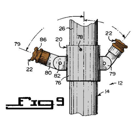 |
FIGURE 9 Figure 9 is an elevational view with parts broken away showing two pivotable target members on the height adjustable collar. |
||||||||||||||||||||||||||||||||||||||||||||||||||||
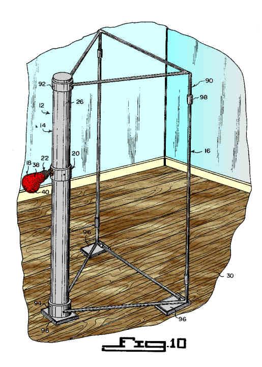 |
FIGURE 10 Figure 10 is a perspective view showing a second embodiment of the instant invention in a room. |
||||||||||||||||||||||||||||||||||||||||||||||||||||
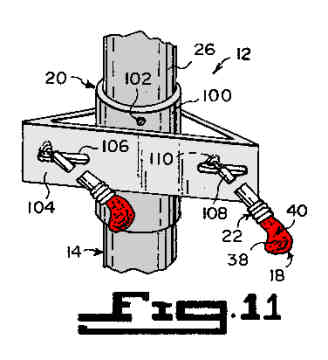 |
FIGURE 11 Figure 11 is a perspective view with parts broken away, showing a special collar with two horizontal adjustable target members used to train hook and speed round house kicks. |
||||||||||||||||||||||||||||||||||||||||||||||||||||
|
|||||||||||||||||||||||||||||||||||||||||||||||||||||