| PATENT DRAWINGS | |||||||||||||||||||||||||||||||||
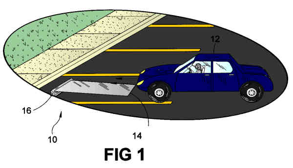 |
FIGURE 1 Shown is a vehicle as it is positioned over said vehicular fluid absorbent pad. Also shown is the ideal size relations of said vehicular fluid pad as it relates to the size of a vehicle. Shown also is the related convenient of setting up said vehicular fluid absorbent pad for use. |
||||||||||||||||||||||||||||||||
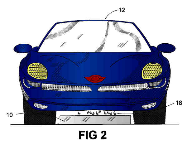 |
FIGURE 2 Figure 2 is a planar view, shwing said vehicular fluid absorbent pad positioned underneath a leaking vehicle. Shown also is length and height relations of said vehicular fluid absorbent pad as it relates to the space available between a vehicles wheel span. Also shown is said vehicular fluid absorbent pad as it prevents leaking fluid from a vehicle from inadvertently damaging the surrounding ground environment. |
||||||||||||||||||||||||||||||||
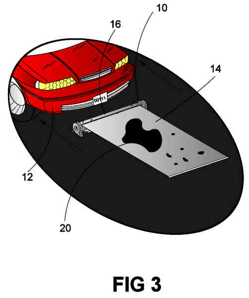 |
FIGURE 3 Figure 3 is a vehicle as it reverses to reveal said vehicular fluid absorbent pad. Also shown is the vehicular fluid absorbent pad as it retains a fluid spill that was emitted from the vehicle. Shown also is the vehicular fluid absorbent pad in its extended position. |
||||||||||||||||||||||||||||||||
 |
FIGURE 4 Figure 4 is the displacement relations between several of the intricate components that comprise said vehicular fluid absorbent pad. Also shown is the ideal shape of said vehicular fluid absorbent pad as it seems fit for the performance of its desired function. Shown also is the vehicular fluid absorbent pad with its absorbing element in the retracted position. |
||||||||||||||||||||||||||||||||
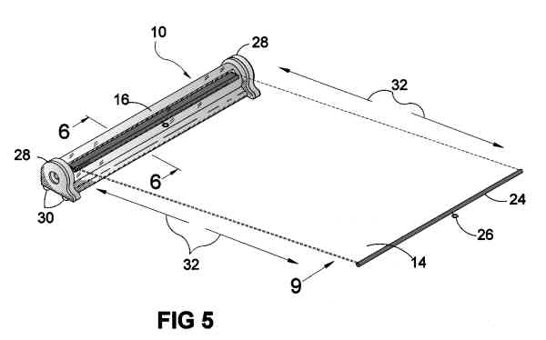 |
FIGURE 5 Figure 5 is the vehicular fluid absorbent pad with its absorbing member in phantom lines. Also shown is the absorbing member in the extended position. Shown also is function directions of the absorbing member (represented by arrows). |
||||||||||||||||||||||||||||||||
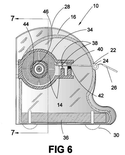 |
FIGURE 6 Figure 6 is a sectional view taken from Figure 5 as indicated. Shown is the displacement relation of the internal intricate components that comprise said vehicular fluid absorbent pad. Also shown is the functional relations of the guides baffle's intricate components as they relate to the absorbing element. Shown also the absorbing element as it protrudes through the main enclosure with the stopper attached to one of its distal ends. Also shown are the rubber feet positioned at the rear and the front most ends of said vehicular of said vehicular fluid absorbent pad. Shown also is the displacement relations of the main enclosure as it relates to the retaining end cap to provide the housing and containment for the internal intricate components of said vehicular fluid absorbent pad. Also shown is the counter weight element as it is positioned in the main enclosure of said vehicular fluid absorbent pad. |
||||||||||||||||||||||||||||||||
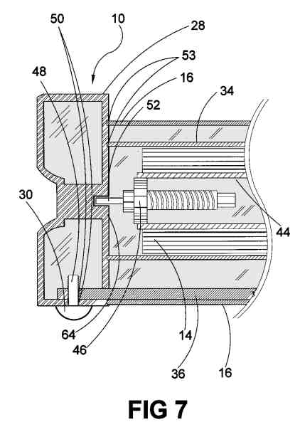 |
FIGURE 7 Figure 7 is a sectional view taken from Figure 6 as indicated. Shown is the linear displacement relations between several of the intricate internal components that comprise said vehicular fluid absorbent pad. Also shown is the coupling relations betwen the rubber feet and the counterweight element as well as the retaining end caps via the threaded member of the rubber feet and the threaded apertures of the counterweight element and the retaining end cap. Shown also is the spring loaded ratchet mechanism as it relates to the retaining end cap. Also shown is the functional and assembly relations of the spring loaded ratchet mechanism and the barrel element. Shown also is the main enclosure as well as the guide baffle coupled to the retaining end caps via the retaining end caps channel grooves. |
||||||||||||||||||||||||||||||||
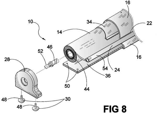 |
FIGURE 8 Figure 8 is an exploded view of the present invention. Shown is the displacement relations of said vehicular fluid absorbent pads intricate components as they would appear in an assembly print for manufacturing. |
||||||||||||||||||||||||||||||||
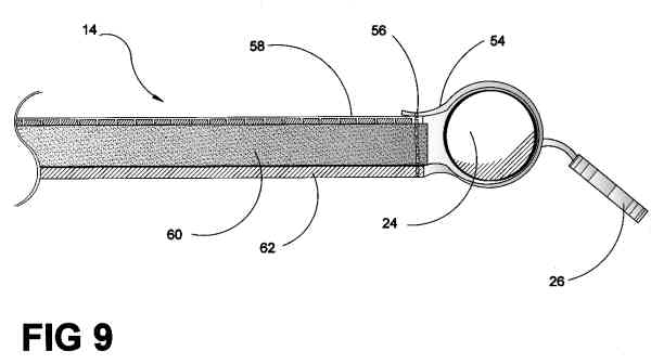 |
FIGURE 9 Figure 9 is a side view, shown the material composition of the absorbent element of the vehicular fluid absorbent pad. Also shown is the linear displacement relations of the materials that compose the absorbent element as they relate to each other. Shown is the stopper sheaf as it works in conjunction with a sewn in thread retainer to assist in providing the material restaining means for the absorbent element. |
||||||||||||||||||||||||||||||||
|
|||||||||||||||||||||||||||||||||